Fault reader -V.A.G 1551- or vehicle system tester -V.A.G 1552- with diagnosis cable -V.A.G 1551/3C-
t
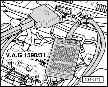
Adapter lead, 121-pin -V.A.G 1598/31-
t
Hand multimeter -V.A.G 1526C- or multimeter -V.A.G 1715-
t
Adapter set -V.A.G 1594C-
Test procedure
l
Engine must be cold.
–
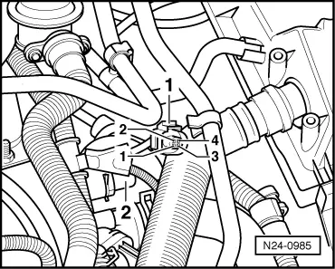
Pull 2-pin connector off map-controlled engine cooling thermostat.
–
Measure resistance of heater element of map-controlled engine cooling thermostat using adapter cables from auxiliary measuring set -V.A.G 1594C-. Specification at 25 °C: 14...16 Ω.
Connect fault reader -V.A.G 1551- (vehicle system tester -V.A.G 1552-). Start engine and select “Address word” 01 of engine control unit. Connect fault reader and select engine control unit → Rep. Gr.01.
Indicated on display:
–
Press keys 0 and 8 for function “Read measured value block” and confirm entry with Q key.
Rapid data transfer HELP
Select function XX
Indicated on display:
–
Press keys 1, 3 and 1 for “Display group number 131” and confirm entry with Q key.
Read measured value block Help
Input display group number XXX
Indicated on display: (1...4 = display zones)
–
Connect multimeter to measure voltage at contacts 1 and 2 of 2-pin connector for thermostat (wiring harness side)
Read measured value block 131 -
1 2 3 4
–
Pull 4-pin connector -1- off coolant temperature sender -G62--2-.
–
Allow engine to continue to run at idling speed and observe the left "bit" in display zone 4: if after a couple of seconds a “1” is displayed (fault detected) the duty cycle of the thermostat must change to 100% in display zone 3.
–
Now read voltage on multimeter. Specification: approx. alternator voltage.
If the specification is attained:
–
Reconnect 4-pin connector to coolant temperature sender -G62- again.
Connect 121-pin adapter cable -V.A.G 1598/31- to control unit wiring harness. The engine control unit remains disconnected.
–
Check wiring between test box and 2-pin connector for open circuit referring to current flow diagram. Contact 2 and test box socket 116, wiring resistance: max. 1.5 Ω.
–
Additionally check wire for short circuit to battery positive and earth. Specification: ∞ Ω.
If no fault can be detected in the wiring and the resistance of the thermostat heating element is OK. Check function of thermostat as follows: