
Golf Mk4
| Parts of cooling system - body side |
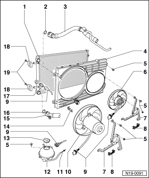
| 1 - | Radiator |
| q | Removing and installing → Chapter. |
| q | After renewing, renew entire coolant. |
| 2 - | O-ring |
| q | Renew |
| 3 - | Upper coolant hose |
| q | Secured to radiator with retaining clip. |
| q | Coolant hose schematic diagram → Chapter. |
| 4 - | Air ducting |
| 5 - | 10 Nm |
| 6 - | Additional fan |
| q | Only vehicles with optional equipment. |
| 7 - | Fan ring |
| 8 - | Retaining clip |
| q | Check for secure seating. |
| 9 - | Connector |
| 10 - | Radiator fan |
| 11 - | To coolant pipe |
| q | Coolant hose schematic diagram → Chapter. |
| 12 - | Expansion tank |
| q | Test for leaks in cooling system using cooling system tester -V.A.G 1274- and adapter for cooling system tester -V.A.G 1274/8-. |
| 13 - | Cap |
| q | Check using cooling system tester -V.A.G 1274- and adapter for cooling system tester -V.A.G 1274/9-. |
| q | Test pressure: 1.4...1.6 bar. |
| 14 - | Bracket |
| q | For radiator fan connector. |
| 15 - | Lower coolant hose |
| q | Secured to radiator with retaining clip. |
| q | Coolant hose schematic diagram → Chapter. |
| 16 - | O-ring |
| q | Renew |
| 17 - | Radiator thermal switch -F18- engine codes AEH, AKL or coolant temperature sender at radiator outlet -G83- engine code APF |
| q | Thermal switch |
| q | Switching temperatures: Stage 1 on: 92...97 °C off: 84...91 °C, Stage 2 on: 99...105 °C off: 91...98 °C. |
| q | Checking coolant temperature sender at radiator outlet -G83- → Chapter (only engine code APF) |
| 18 - | Bracket |
| q | For radiator. |
| q | Note installation position. |
| q | Note different versions |
| 19 - | 10 Nm |