volkswagen Workshop Repair Guides

Volkswagen Workshop Service and Repair Manuals

Piston and cylinder dimensions > < Crankshaft dimensions
4cyl. Injection Engine, (2.0 ltr. Engine) (Mexico)
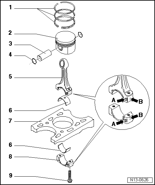
Dismantling and assembling piston and conrod
 
N13-0626
  • Piston rings
    • ◆ Offset gaps by 120 °
    • ◆ Use piston ring pliers to remove and install
    • ◆ Manufacturer's mark faces towards piston crown
    • ◆ Checking ring gap=> fig. 1
    • ◆ Checking ring to groove clearance => fig. 2
  • Piston
    • ◆ Checking => fig. 3
    • ◆ Mark installation position and cylinder number
    • ◆ Arrow on piston crown points to belt pulley end
    • ◆ Install using piston ring clamp
  • Piston pin
    • ◆ If difficult to remove, heat piston to 60 °C
    • ◆ Remove and install with VW 222a
 
N13-0626
  • Circlip
  • Conrod
    • ◆ with cracked bearing cap
    • ◆ Only renew as a set
    • ◆ Mark allocation to cylinder -B-
    • ◆ Installation position:
      Marking -B- faces towards belt pulley end
  • Bearing shell
    • ◆ Observe installation position=>
      Fig. 4
    • ◆ Insert bearing shells centrally
    • ◆ Do not interchange used bearing shells
    • ◆ Check seated securely
    • ◆ Axial clearance
      New: 0.10 ... 0.35 mm
      Wear limit: 0.4 mm
    • ◆ Check radial clearance with Plastigage:
      New: 0.01 ... 0.05 mm
      Wear limit: 0.09 mm
      Do not rotate crankshaft when checking radial clearance
 
N13-0626
  • Cylinder block
    • ◆ Checking cylinder bore
      =>Fig. 5
    • ◆ Piston and cylinder dimensions
      =>Page 13-44
  • Conrod bearing cap
    • ◆ Observe installing position
    • ◆ The caps only fit in one position and only on the appropriate conrod, this is due to the breaking procedure (industrially cracking) separating the cap from the conrod
  • 30 Nm + 1/4 turn (90 °) further
    • ◆ Torx E 10
    • ◆ Renew
    • ◆ Oil thread and contact surface
    • ◆ To measure radial clearance tighten to 30 Nm, but do not turn further
 
V13-0016

→ Fig. 1    Checking piston ring gap

Special tools, testers, measuring instruments and auxiliary items required

  • ◆ Feeler gauge

Test sequence

  • ‒ Push ring squarely from above down to approx. 15 mm from bottom end of cylinder.

Piston ring

Gap

New

Wear limit

Compression rings

mm

0.20...0.40

0.8

Oil scraper ring

mm

0.25...0.50

0.8

 
V13-0687

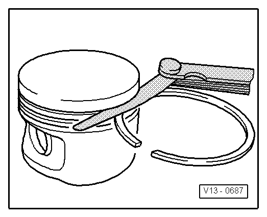
→ Fig. 2    Checking ring to groove clearance

Special tools, testers, measuring instruments and auxiliary items required

  • ◆ Feeler gauge

Test sequence

Clean groove before checking.

Piston ring

Ring to groove clearance

New

Wear limit

Compression rings

mm

0.06...0.09

0.20

Oil scraper ring

mm

0.03...0.06

0.15

 
V13-0010

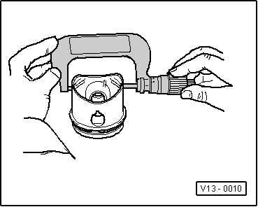
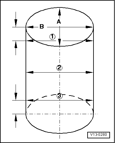
→ Fig. 3    Checking piston

Special tools, testers, measuring instruments and auxiliary items required

  • ◆ External micrometer 75 ... 100 mm

Test sequence

Measure pistons approx. 10 mm from the lower edge of skirt, 90 ° offset to the axis of the piston pin.

Deviation from nominal dimension
    max. 0.04 mm

 
N13-0671

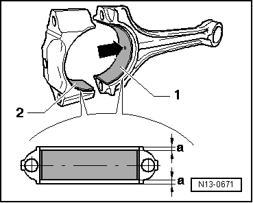
→ Fig. 4    Installation position of bearing shells

Bearing shell-1- with oil channel-arrow- for conrod.

Bearing shell-2- without oil channel conrod bearing cap.

  • ‒ Insert bearing shells and conrod bearing cap centrally.

The dimension -a- must be the same on both the left and the right side.

 
V13-0280

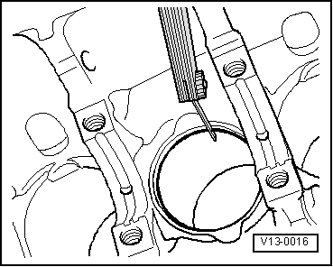
→ Fig. 5    Checking cylinder bores

Special tools, testers, measuring instruments and auxiliary items required

  • ◆ Internal dial gauge 50 ... 100 mm
  • ◆ Measure bores at 3 locations in both directions -A- across the engine and -B- in line with crankshaft.
  • ◆ Deviation from nominal dimension
        max. 0.08 mm

Note:

Measuring the cylinder bores must not be done when the cylinder block is mounted on a repair stand with adapter bracket VW 540, as incorrect measurements would then be possible.

Piston and cylinder dimensions > < Crankshaft dimensions