
Golf Mk4
|
Removing and installing parts of fuel supply system
Checking fuel pump
|
 |
|
Test prerequisites |
 |
|
Note: Observe description of function of crash fuel shut-off. Checking function and voltage supply
If the fuel pump does not run:
|
 |
|
Fuel pump runs:
=> Current flow diagrams, Electrical fault finding and Fitting locations Fuel pump does not run: |
 |
|
|
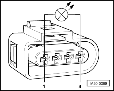 |
|
LED does not light up:
=> Current flow diagrams, Electrical fault finding and Fitting locations LED lights up (voltage supply OK.): |
 |
|
If no open circuit can be found:
Checking delivery rate Test prerequisites
Test sequence
Warning:
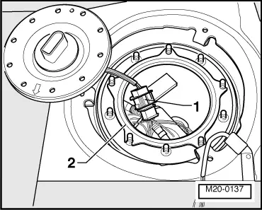
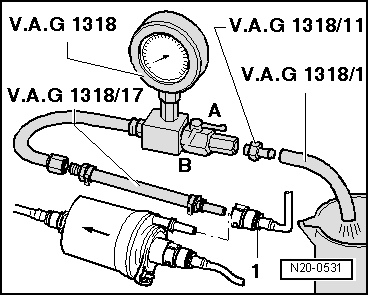
Fuel system is under pressure! Before opening the system place a cloth around the connection. Then release pressure by carefully loosening the connection. |
 |
|
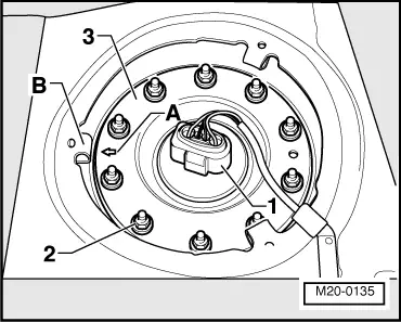
Note: To do this slide safety ring -2- into the union -1-. |
 |
|
|
 |
|
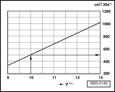
*) Minimum delivery cm3/30 seconds **) Voltage at fuel pump with engine at rest and pump running (approx. 2 volts less than battery voltage). Example: During the test, a voltage of 12,0 volts is measured at the battery. As the voltage at the pump is approx. 2 volts less than the battery voltage, the result is a minimum delivery of approx. 500 cm3/30 seconds. If the minimum delivery rate is not attained:
If the fuel pressure regulator is OK.:
If the supply pipe is OK.:
|
 |
|
|
 |
|
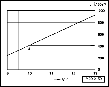
*) Minimum delivery cm3/30 seconds **) Voltage at fuel pump with engine at rest and pump running (approx. 2 volts less than battery voltage). Note: Due to the operating of the suction jet pump the minimum delivery rate before the fuel filter/pressure regulator is lower. Example: During the test, a voltage of 12,0 volts is measured at the battery. As the voltage at the pump is approx. 2 volts less than the battery voltage, the result is a minimum delivery of approx. 415 cm3/30 seconds. If the minimum delivery rate is now attained:
If the minimum delivery rate is again not attained:
Only if you have not detected any faults up to now:
If the delivery rate has been attained but you still suspect a fuel supply system fault (e.g. intermittent failure of fuel supply system):
|
 |
|
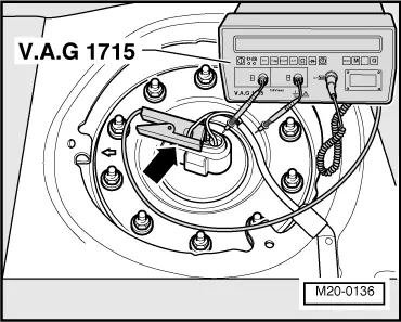
Note: If the fuel system malfunction is intermittent, a check during a road test can be performed with the help of a 2nd person. If the current draw exceeds:
Check non-return valve for fuel pump Test prerequisites
|
|
|
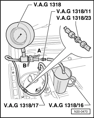
Warning:
Danger of spray when opening the shut-off-tap; hold container in front of the free connection on the pressure gauge.
If the pressure drops further:
If no wiring fault is detected:
|