volkswagen Workshop Repair Guides

Volkswagen Workshop Service and Repair Manuals

General notes on injection > < Servicing injection system
4cyl. Injection Engine, (2.0 ltr. Engine) (Mexico)
Servicing injection system
Fitting locations overview

The components A, B C and D are not shown on the illustration.

  •     A -    Brake pedal switch (F47) or brake light switch (F)
    • ◆ Together in one housing in the footwell
  •     B -    Accelerator pedal position senders (G79 and G185)
    • ◆ In footwell at accelerator pedal
  •     C -    Clutch pedal switch (F36)
    • ◆ In footwell
  •     D -    Fuel pressure regulator
    • ◆ On fuel filter in fuel tank
    • ◆ Checking => Page 24-38
 
M24-0335
  • Inlet camshaft timing adjustment valve (N205)
    • ◆ is controlled by the engine control unit
  • Combi-valve
    • ◆ Secondary air system
  • Hall sender (G40)
    • ◆ In cylinder head cover
  • 81-pin connector
    • ◆ Only disconnect or connect with ignition switched off
    • ◆ Release to disconnect
  • Engine control unit
    • (Motronic control unit -J220-)
    • ◆ On replacement, the control unit must be matched to the electronic immobilizer => Page 24-43, adapting components
    • ◆ Fitting location: In plenum chamber
    • ◆ Renew => Page 24-41
 
M24-0335
  • 40-pin connector
    • ◆ Only disconnect or connect with ignition switched off
    • ◆ Release to disconnect
  • Coolant temperature sender (G62)
    • ◆ For engine control unit
    • ◆ Gold plated contacts
    • ◆ Release pressure in coolant system if necessary before removing components
  • Activated charcoal canister solenoid valve 1 (N80)
    • ◆ Activated charcoal canister system=> Page 20-55:
  • Intake manifold
    • Upper part:
    • ◆ Dismantling and assembling => page 24-13
    • Lower part:
    • ◆ Dismantling and assembling => page 24-15
 
M24-0335
  • Throttle valve control part (J338)
    • ◆ When renewing, adapt (match) engine control unit to throttle valve control part =>Seite 24-43, adapting components
    • ◆ 6-pin connector
    • ◆ Gold plated contacts
  • Heater element (N79)
    • ◆ For crankcase breather
    • ◆ Checking => page 24-17, item 1
  • Air mass meter (G70) with intake air temperature sender (G42)
    • ◆ Gold plated contacts
  • Protective housing for relays
    • ◆ Secondary air pump relay (J299)
    • ◆ Motronic current supply relay (J271)
    • ◆ Relay assignment in protective housing=> fig.1
 
M24-0335
  • Air cleaner
    • ◆ Dismantling and assembling => page 24-17
  • Main fuses
  • Lambda probe downstream of catalytic converter (G130), 50Nm
    • ◆ Fitting location: In rear of catalytic converter
    • ◆ When renewing erase fault memory => page 24-46
    • ◆ Removing and installing => page 26-1
  • 4-pin connector
    • ◆ Brown
    • ◆ Connector contacts 3 and 4 are gold plated
    • ◆ For Lambda probe after catalytic converter (G130) and Lambda probe heating (Z29)
    • ◆ Fitting location: On right on underside of vehicle => Fig.2
 
M24-0335
  • Centre Lambda probe catalyst (G465), 50 Nm
    • ◆ Fitting location: In centre catalyst
    • ◆ When renewing erase fault memory => page 24-46
    • ◆ Removing and installing => page 26-1
  • 4-pin connector
    • ◆ black
    • ◆ Connector contacts 3 and 4 are gold plated
    • ◆ For centre Lambda probe catalyst (G465) and Lambda probe heater (Z59)
    • ◆ Fitting location: On right on underside of vehicle => Fig.2
 
M24-0335
  • Exhaust gas temperature sender 1(G235), 45 Nm
    • ◆ Fitting location: In exhaust pipe
    • ◆ When renewing erase fault memory => page 24-46
    • ◆ Removing and installing => page 26-1
  • Lambda probe upstream of catalytic converter (G39), 50Nm
    • ◆ Fitting location: In exhaust manifold
    • ◆ When renewing erase fault memory => page 24-46
    • ◆ Removing and installing => page 26-1
 
M24-0335
  • 6-pin connector
    • ◆ Black for Lambda probe before catalytic converter (G39) and Lambda probe heater (Z19)
    • ◆ Gold plated contacts
    • ◆ Fitting location: On right on underside of vehicle => Fig.2
  • 2-pin connector
    • ◆ Black for exhaust gas temperature sender (G235)
    • ◆ Gold plated contacts
    • ◆ Fitting location: On right on underside of vehicle => Fig.2
  • Knock sensor 1 (G61)
    • ◆ Gold plated contacts
    • ◆ Torque setting:
      => Page 28-3, item 9
  • Knock sensor 2 (G66)
    • ◆ Next to ignition transformer
    • ◆ Gold plated contacts
    • ◆ Torque setting:
      => Page 28-3, item 9
 
M24-0335
  • Injector (N30...N33)
    • ◆ Air shrouded
    • ◆ Checking quantity injected and for leaks
  • Secondary air pump motor (V101)
    • ◆ Secondary air system
  • Engine speed sender (G28)
    • ◆ Torque setting 10 Nm
  • Ignition coils with final output stages (N70, N127, N291, N292)
    • ◆ => Page 28-2, item 2
 
M26-0086

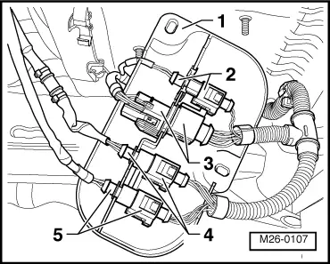
→ Fig.1    Position of relays in protective housing (on left in engine compartment)

  •     1 -    Secondary air pump relay (J299),
    Distinguishing features: Control number 100
  •     2 -    Motronic current supply relay (J271),
    Distinguishing features: Control number 428

Notes:

  • ◆ The relay locations may differ depending on level of equipment.
    For latest control numbers and fitting locations:

=> Current flow diagrams, Electrical fault finding and Fitting locations

  • ◆ Disconnect battery earth strap first if tools are required to pull relays or control units out of the relay plate.
 
M26-0107
  • ◆ Before disconnecting battery earth strap obtain code for radios with anti-theft coding.

→ Fig.2    Connectors´ fitting location

  •     1 -    Protective housing, on vehicle underside right side
  •     2 -    For exhaust gas temperature sender 1 (G235)
  •     3 -    For Lambda probe before catalytic converter (G39)
  •     4 -    For centre Lambda probe catalyst (G465)
  •     5 -    For Lambda probe after catalyst (G130)

General notes on injection > < Servicing injection system