volkswagen Workshop Repair Guides

Volkswagen Workshop Service and Repair Manuals

Installing > < Removing and installing cylinder head
Removing
Removing
  Caution
When doing any repair work, especially in the engine compartment, pay attention to the following due to the cramped conditions:
t  Route all the various lines (e.g. for fuel, hydraulics, activated charcoal filter system, coolant, refrigerant, brake fluid and vacuum) and electrical wiring in their original positions.
t  To avoid damage to lines, ensure sufficient clearance to all moving or hot components.
–  First check whether a coded radio is fitted. If so, obtain anti-theft coding.
–  With ignition switched off, disconnect earth strap from battery.
–  All cable ties which are opened or cut open when engine is removed must be replaced in the same position when engine is installed.
–  Remove intake manifold → Chapter.
   
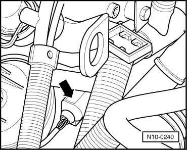
–  Pull 4-pin connector off coolant temperature sender -G62- with coolant temperature gauge sender -G2--arrow-.
–  Drain coolant → Chapter.
–  Now remove thermostat housing → Chapter.
  N10-0240
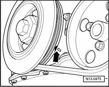
–  Turn crankshaft at securing bolt of vibration damper in engine DOR to TDC no. 1 cylinder marking -arrow-.
–  Remove cylinder head cover → Chapter.
  N13-0475
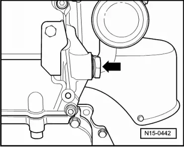
–  Remove tensioner for camshaft roller chain -arrow-.
  N15-0442
–  Before removing mark camshaft roller chain (e.g. with paint, arrow pointing in direction of rotation).
  Note
Do not mark chain with a centre punch or any similar means!
–  Pull off connectors from following components of cover part:
t  Continued coolant circulation pump -V51-
t  Inlet camshaft control valve 1 -N205-
t  Exhaust camshaft control valve 1 -N318-
t  Hall sender -G40-
t  Hall sender 2 -G163-
  Note
Before pulling off connectors, mark allocation of each connector to component.
–  Move wiring harness clear.
–  Remove cover part of camshafts → Chapter.
Front-wheel drive vehicles
–  Unbolt front exhaust pipe from exhaust manifold → Chapter.
Vehicles with four-wheel drive
–  Unbolt front exhaust pipe from exhaust manifold → Chapter.
Continuation for all vehicles
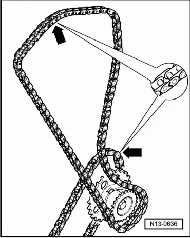
  N13-0636
–  Now check valve timing: TDC no. 1 cyl. setting is correct if a groove can be seen on the chain sprockets of the intermediate shaft -arrow-.
  Note
This condition is only reached at every 2nd TDC position.
If the groove cannot be seen:
–  Turn crankshaft one full turn further in direction of engine rotation.
  Note
When the crankshaft is turned, the tensioning rail (as opposed to the chain tensioner) must be pressed against the camshaft roller chain by hand.
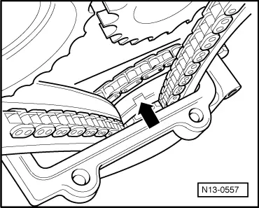
  N13-0557
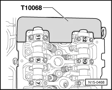
–  Camshaft bar -T10068 A- must engage in grooves in both shafts.
  Note
If camshaft bar cannot be fitted, turn crankshaft in direction of engine rotation up to approx. 5 mm past TDC setting for no. 1 cylinder (dependent on drive chain tolerances).
Check setting marks of camshaft adjusters against marks on valve timing housing:
  N15-0468
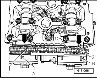
–  Arrows -A- and -B- on camshaft adjusters must align with notches -arrows- in valve timing housing -C-.
–  First remove exhaust camshaft adjuster and then inlet camshaft adjuster.
  Note
  N13-0661
Only counterhold camshaft with AF 32 mm open-jaw spanner -arrow-. Camshaft bar -T10068 A- must not be fitted when chain sprockets are loosened or tightened.
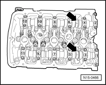
  N15-0466
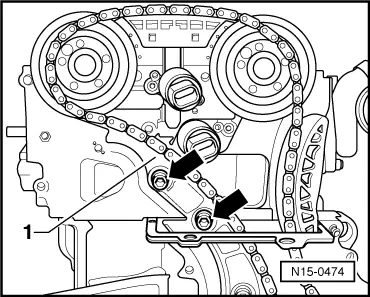
–  Unscrew securing bolts -arrows- and remove guide rail securing bolt -1-.
–  Lay camshaft roller chain aside.
  N15-0474
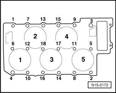
–  Loosen cylinder head bolts in prescribed sequence and remove completely.
  Note
Use key -3452- for polydrive cylinder head bolts.
–  Carefully lift cylinder head off.
  N15-0172

Installing > < Removing and installing cylinder head