volkswagen Workshop Repair Guides

Volkswagen Workshop Service and Repair Manuals

Removing and installing cylinder head > < Assembly overview - cover part
Removing and installing cylinder head cover
Special tools and workshop equipment required
   
t  Spring-type clip pliers -VAS 5024A-
  W00-1179
t  
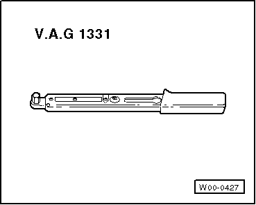
Torque wrench -V.A.G 1331-
t  Puller -T10095 A-
Removing
  Caution
When doing any repair work, especially in the engine compartment, pay attention to the following due to the cramped conditions:
t  
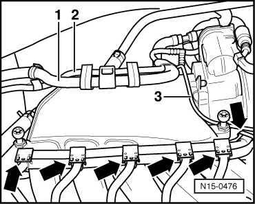
Route all the various lines (e.g. for fuel, hydraulics, activated charcoal filter system, coolant, refrigerant, brake fluid and vacuum) and electrical wiring in their original positions.
t  To avoid damage to lines, ensure sufficient clearance to all moving or hot components.
–  First check whether a coded radio is fitted. If so, obtain anti-theft coding.
–  With ignition switched off, disconnect earth strap from battery.
–  All cable ties which are opened or cut open when engine is removed must be replaced in the same position when engine is installed.
–  Remove engine cover.
–  Remove air cleaner → Chapter.
–  Remove intake hose and intake connecting flange between air mass meter and throttle valve module → Chapter.
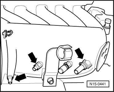
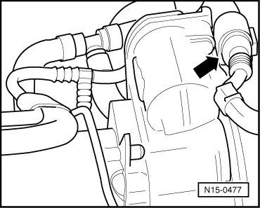
–  Pull off connecting hose of crankcase breather between cylinder head cover and intake hose on cylinder head cover.
  Note
To do this, press down buttons on hose couplings.
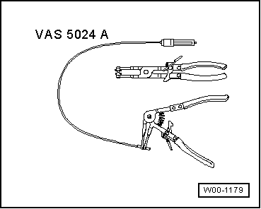
–  Remove ignition coils with output stages using puller -T10095 A-.
  W00-0427
–  Unclip wiring harness of ignition coils out of cable guide -arrows-.
–  Unclip coolant hose -1-, breather line of activated charcoal filter system -2- and vacuum line -3- on intake manifold.
  N15-0476
–  Pull off 6-pin connector on throttle valve module -arrow-.
  WARNING
Steam may escape when expansion tank is opened. Wear protective glasses and clothing to avoid eye injuries and scalding. Cover cap with cloth and open carefully.
–  Open and close expansion tank cap to release pressure in cooling system.
–  Pull off coolant hoses from throttle valve module and seal hose ends.
  N15-0477
–  Unscrew earth connection from wiring harness bracket -arrow-.
  WARNING
Fuel system is under pressure! Wear protective glasses and gloves to avoid injuries and skin contact. Before opening the system place a cloth around the connection. Then release pressure by carefully loosening the connection.
  N15-0472
–  Pull off fuel supply line -1- (with white marking) and fuel return line -2- (with blue marking) off fuel rail and catch fuel that escapes in a cloth.
–  Seal lines so that fuel system is not contaminated by dirt.
  N24-1280
–  Unscrew cable guide for fuel lines, breather line of activated charcoal filter system and wiring harness on cylinder head cover -arrows-.
  N15-0473
–  Now pull vacuum lines -arrows- off intake manifold.
  Note
To do this, press down buttons on hose couplings.
–  Unclip pressure hose between combination valve and secondary air pump motor and all other lines from retainers on intake manifold and cylinder head cover.
–  Unscrew cable guide for coolant hoses and wiring harness on cover part → Item.
–  Pull vacuum hose off intake manifold changeover vacuum actuator.
–  Remove the two bolts on the side for the intake manifold support.
–  Pull connectors off thermal switch and radiator fan.
–  Remove front bumper: → General body repairs, exterior; Rep. Gr.63
–  Bring lock carrier into service position → General body repairs, exterior; Rep. Gr.50.
–  Unscrew dipstick guide tube from intake manifold.
–  Unscrew securing bolts of intake manifold and remove intake manifold together with throttle valve module.
–  Remove intake manifold and place it on a suitable surface so that the vacuum actuator will not be damaged.
  Note
Seal intake ports in intake manifold and in cylinder head with clean cloths.
–  Remove cylinder head cover.
Installing
Installation is carried out in the reverse order. When installing, note the following:
  Note
t  Replace cylinder head cover if damaged or leaking.
t  Bolt intake manifold first to cylinder head. Then tighten both bolts of intake manifold support.
t  Ensure that fuel hoses are tight.
–  If necessary fill with coolant → Chapter.
Torque settings
  N15-0441
Threaded connectionTorque setting
Cylinder head cover to cylinder head8 Nm
Intake manifold to cylinder head13 Nm
Intake manifold to support23 Nm
Dipstick guide tube to intake manifold8 Nm


Removing and installing cylinder head > < Assembly overview - cover part