volkswagen Workshop Repair Guides

Volkswagen Workshop Service and Repair Manuals

Crash fuel shut-off > < Rules for cleanliness
Removing, installing and checking suction jet pump: vehicles with four-wheel drive
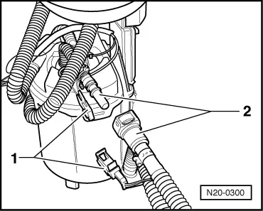
On vehicles with four-wheel drive, fuel is pumped from the area of fuel gauge sender 2 -G169-, → Item, to the fuel delivery unit by means of a suction jet pump due to the shape of the fuel tank. The suction jet pumps work according to one of the rules of physics. It functions via the fuel supply via an additional connection from fuel pump.
  Note
t  Checking is only necessary if:
t  the engine stops due to lack of fuel
t  fault codes (V.A.G codes) “17536, 17538, 17544 and 17546” are stored in the fault memory even though the fuel gauge shows that the fuel tank is 1/4 full.
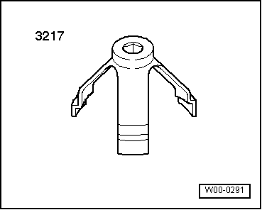
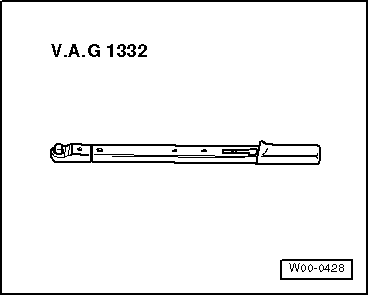
Special tools and workshop equipment required
   
t  Union nut tool -3217-
  W00-0291
t  Torque wrench -V.A.G 1332-
Prerequisite
l  Fuel tank must have been drained
l  Both senders have been checked with fault finding program and are OK → Current flow diagrams, Electrical fault finding and Fitting locations
Procedure
–  Note safety precautions before beginning work → Chapter.
–  First check whether a coded radio is fitted. If so, obtain anti-theft coding.
–  With the ignition switched off, disconnect battery earth strap.
  WARNING
Fuel system is under pressure! Wear protective glasses and gloves to avoid injuries and skin contact. Before loosening hose connections, wrap a cloth around the connection. Then release pressure by carefully pulling hose off connection.
–  Pull 4-pin connector and fuel hoses off fuel delivery unit (right-hand side of vehicle) and remove the fuel delivery unit → Chapter.
  Note
To do this, press down buttons on hose couplings.
  W00-0428
–  Now disconnect 2-pin connector -1-, and fuel supply hose coupling -2- to suction jet pump.
  Note
To do this, press down buttons on hose couplings.
  N20-0300
–  Lift fuel delivery unit slightly and pull bracket with return line -arrow- off upwards.
  N20-0279
–  Now unscrew union nut of fuel gauge sender 2 -G169- on left-hand side of vehicle.
–  Lift fuel gauge sender 2 -G169- upwards as far as possible.
  N20-0301
–  Separate cable tie on fuel line -arrow- and carefully open out mounting of suction jet pump on fuel gauge sender 2 -G169-.
–  Now unclip suction jet pump with supply and return line on fuel gauge sender 2 -G169- and remove.
–  Check that the fuel lines on suction jet pump are fitted securely and are not damaged.
–  Additionally check suction jet pump for possible soiling.
If no fault is found:
–  Install suction jet pump and fuel gauge sender 2 -G169- in reverse order of removal.
  Note
t  Before installing fuel delivery unit or fuel gauge sender 2 -G169-, ensure that seal has been inserted dry in opening of fuel tank.
t  Moisten seal with fuel only when installing flange or fuel delivery unit.
t  Ensure that fuel hoses are tight.
  N20-0302

Crash fuel shut-off > < Rules for cleanliness