
Golf Mk4
| Repairing refrigerant circuit components |
 Note
Note| t | The refrigerant must be extracted beforehand, e.g. with air conditioning service station -VAS 6007A-. |
| t | The previously used service stations can still be used ⇒ Volkswagen Workshop Equipment catalogue. |
| t | Safety measures when working on an evacuated refrigerant circuit → Chapter. |
| t | Only the components marked with an “*” can be replaced without opening and evacuating. |
| t | All of the refrigerant circuit's components that have been opened must be sealed with suitable plugs to prevent the ingress of moisture. |
| t | The colour coding of O-rings for R134a refrigerant circuits has been discontinued. Coloured and black O-rings are used. |
| t | Moisten threaded connections of refrigerant circuit with polyethylene glycol (PEG) VW part number 294440 before installation. |
| t | Under certain conditions, it is no longer necessary to renew the receiver each time the refrigerant circuit is opened → Rep. Gr.00Technical information “Air conditioning systems - with refrigerant R134a VW” Renewing parts. |
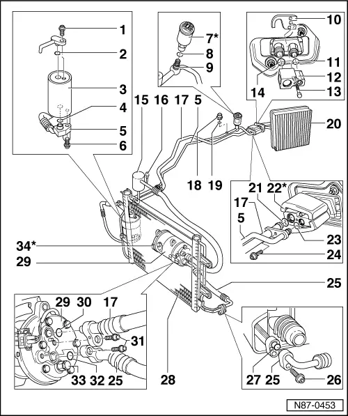
| 1 - | Bolt |
| q | 15 Nm. |
| 2 - | O-ring |
| q | 10.8 mm; 1.8 mm. |
| 3 - | Receiver with dryer bag |
| q | Functions → Chapter. |
| 4 - | O-ring |
| q | 10.8 mm; 1.8 mm. |
| 5 - | Refrigerant line |
| q | From receiver with dryer bag to expansion valve. |
| 6 - | Bolt |
| q | 15 Nm. |
| 7 - | Air conditioning system pressure switch -F129-* or high pressure sender -G65-* |
| Removing and installing: |
| q | Torque setting 8 Nm |
| q | Renew O-ring (note part number). |
| q | Air conditioning system pressure switch -F129- and high pressure sender -G65- can be removed without having to evacuate refrigerant from refrigerant circuit. |
| q | The high pressure sensor -G65- cannot be checked via the Climatronic self-diagnosis, but only via the engine control unit. |
| q | Checking: vehicle diagnosis, testing and information system -VAS 5051B- in guided fault finding. |
| q | The high pressure sensor -G65- supplies information to radiator fan control unit -J293- and engine control unit. |
| q | Check air conditioning system pressure switch -F129- → Chapter. |
| q | Check high pressure sender -G65- → Chapter. |
| Function: |
| q | Switches radiator fan -V7- to next higher speed when pressure increases in refrigerant circuit. |
| q | Switches off the air conditioner when the pressure is high (for example, insufficient engine cooling). |
| q | Switches off the air conditioner when the pressure is too low (for example, loss of refrigerant). |
| 8 - | O-ring |
| q | 10.8 mm; 1.8 mm. |
| 9 - | Schrader valve |
| 10 - | Threaded plate |
| 11 - | O-ring |
| q | 10.8 mm; 1.8 mm. |
| 12 - | Expansion valve |
| q | In engine compartment on right. |
| q | Aperture must be sealed against splashed water. |
| q | Removing → Chapter. |
| Function |
| t | The expansion valve atomises incoming refrigerant and regulates the flow so that, depending on the heat transport, the vapour does not become a gas until it reaches the outlet of the evaporator. |
| t | The expansion valves for R134a refrigerant circuits are marked with a green sticker. |
| 13 - | Bolts |
| q | 8 Nm. |
| 14 - | O-ring |
| q | 14 mm; 1.8 mm. |
| 15 - | Damper |
| q | In refrigerant hose from expansion valve to air conditioner compressor. |
| q | For vehicles with the engine code BDE near the expansion valve. |
| 16 - | Extraction and charging valve |
| q | Low pressure side. |
| q | Releasing refrigerant into the environment is a punishable offence. |
| q | Removing and installing → Chapter. |
| q | Capacities → Chapter. |
| 17 - | Refrigerant hose |
| q | From expansion valve to air conditioner compressor. |
| q | With damper. |
| 18 - | Extraction and charging valve |
| q | High pressure side. |
| q | Releasing refrigerant into the environment is a punishable offence. |
| q | Removing and installing → Chapter. |
| q | Capacities → Chapter. |
| 19 - | O-ring |
| q | 10.8 mm; 1.8 mm. |
| 20 - | Evaporator |
| q | In passenger compartment. |
| q | Removal → Chapter, Dismantling and assembling evaporator housing. |
| 21 - | O-ring |
| q | 16.7 mm; 1.8 mm. |
| 22 - | Heat insulation* |
| 23 - | O-ring |
| q | 7.6 mm; 1.8 mm. |
| 24 - | Bolt |
| q | 8 Nm. |
| 25 - | Refrigerant hose |
| q | From air conditioner compressor to condenser. |
| 26 - | Bolt |
| q | 15 Nm. |
| 27 - | O-ring |
| q | 10.8 mm; 1.8 mm. |
| 28 - | Condenser |
| q | Removing → Chapter. |
| 29 - | Air conditioner compressor |
| q | With air conditioning system magnetic coupling -N25-. |
| q | Repairing air conditioning system magnetic coupling -N25- → Chapter. |
| q | An air conditioner compressor with no air conditioning system magnetic coupling -N25- is installed in vehicles with engine code BAD. Notes → Chapter. |
| 30 - | O-ring |
| q | 14.3 mm; 2.4 mm. |
| 31 - | Bolts |
| q | 20 Nm. |
| 32 - | O-ring |
| q | 10.8 mm; 1.8 mm. |
| 33 - | High-pressure safety valve |
| q | Checking → Chapter. |
| 34 - | Air conditioning system magnetic coupling -N25- |
| Manufacturer Sanden: |
| q | Repairing air conditioning system magnetic coupling -N25- → Chapter. |
| Manufacturer Zexel: |
| q | Repairing air conditioning system magnetic coupling -N25- → Chapter. |