volkswagen Workshop Repair Guides

Volkswagen Workshop Service and Repair Manuals

Performing self-diagnosis > < Self-diagnosis - Guide
5-speed automatic gearbox 09A self-diagnosis
Locations of electrical/electronic components
 
N01-0505
  • Automatic gearbox control unit -J217-
    • ◆ Location
    • ◆ Removing => Page 01-19
    • ◆ Installing => Page 01-20
    • ◆ Checked by self-diagnosis => Carrying out self-diagnosis, Page 01-23
    • ◆ Control unit sends and receives data from data bus =>01-1
  • Engine control unit
    • ◆ Location and removing and installing =>Fig. 1
    • ◆ Location => Fig. 1
    • ◆ Control unit sends and receives data from data bus =>01-1

If engine or gearbox control units are replaced, the system must be brought to basic setting => page 01-46 , Initiating basic setting.

 
N01-0505
  • Dash panel insert with data bus diagnosis interface -J533-
    • ◆ With selector lever position display

=> Electrical system, self-diagnosis; Repair group 01

    • ◆ Control unit sends and receives data from data bus =>01-1
  • Diagnostic connection
    • ◆ Location => Fig. 2
  • Multifunction switch -F125-
    • ◆ Removing, installing and adjusting

=> 5-speed automatic gearbox 09A; Repair group 38; Removing, installing and adjusting multi-function switch -F125-

    • ◆ -F125- is checked by self-diagnosis
  • Intermediate shaft speed sender -G265-
    • ◆ Picks up signal on spur gear A
    • ◆ Location: in gearbox
    • ◆ -G265- is checked by self-diagnosis
 
N01-0505
  • Road speed sender -G68-
    • ◆ Picks up gearbox output speed (road speed)
    • ◆ Location: in gearbox
    • ◆ -G68- is checked by self-diagnosis
  • Gearbox input speed sender -G182-
    • ◆ Picks up gearbox input speed (turbine shaft)
    • ◆ Location: in gearbox
    • ◆ Checked by self-diagnosis
  • Valve chest
    • ◆ Location: in gearbox

=> 5-speed automatic gearbox 09A; Repair group 38; Removing and installing valve chest

    • ◆ The solenoid valves -N88-, -N89-, -N90-, -N91-, -N92-, -N93-, -N281-, -N282- and -N283- are attached to the valve chest
    • ◆ The valves are checked by self-diagnosis
 
N01-0505
  • Oil temperature sender (ATF) -G93-
    • ◆ Location: in gearbox
  • Solenoid for selector lever lock -N110-
    • ◆ Location and removing and installing

=> 5-speed automatic gearbox 09A; Repair group 37; Removing and installing solenoid for selector lever lock -N110-

    • ◆ The solenoid is checked by self-diagnosis
    • ◆ Can be checked in measured value block => page 01-61
  • Brake pressure switch -F270-
    • ◆ Signal can be checked in measured value block => Page 01-48 .
    • ◆ Location: switch is located on bulkhead in brake pipe to front right-hand wheel
 
N01-0505
  • Brake light switch -F-
    • ◆ Location and removing and installing =>Fig. 3
    • ◆ Can be checked electrically => page 01-48
  • Relay for starter lock-out and reversing light -J226-
    • ◆ Location => Fig.4
 
N37-0805

→ 16 - Tiptronic switch -F189-

  • ◆ Fitting location: The switch is on the printed circuit of the symbol insert, which is located in the selector mechanism cover.
  • ◆ It consists of 3 Hall sensors, which are actuated by solenoids
  • ◆ The switch can be checked in the measured value block => page 01-61
  • ◆ If faults occur in the switch, the symbol insert must be renewed with the printed circuit
  • ◆ Repair group 37; Servicing selector mechanism; Dismantling and assembling selector mechanism
 
N01-0138

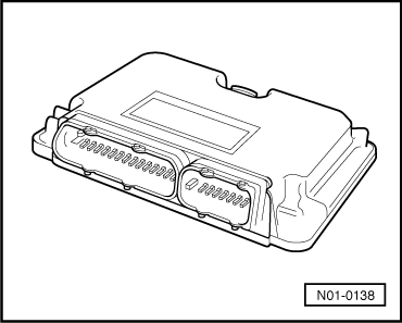
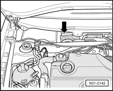
→ Fig.1     Engine control unit

Location: The control unit is located in plenum chamber.

Removing and installing control unit

=> Repair group 24 or 25

 
N01-0137

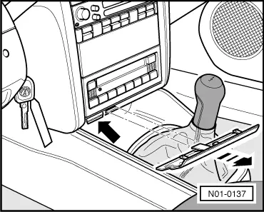
→ Fig.2     Diagnosis connections

Location: The diagnosis connection -arrow- is located behind the cover above the ashtray.

 
N37-0155

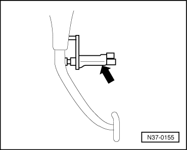
→ Fig.3     Brake light switch -F-

Location: Brake light switch (arrow) is located on pedal cluster.

Removing and installing brake light switch

=> Repair group 47; Assembly overview: Pedal cluster, brake pedal

 
N01-0143

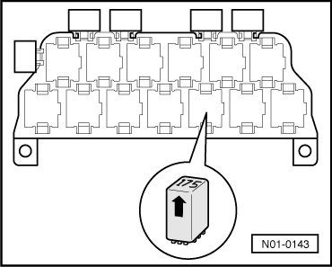
→ Fig.4     Relay for starter inhibitor and reversing light -J226-

Location: Relay located on additional relay carrier under dash panel, left.

Relay is marked with number "175" -arrow-.

 
N01-0142

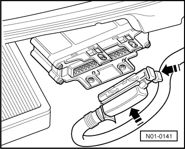
Location of control unit for automatic gearbox -J217-

→ The control unit -arrow- is located in plenum chamber centre/right.

 
N01-0140

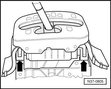
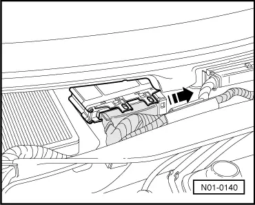
Removing control unit

  • ‒ Switch off ignition, open bonnet.
  • ‒ Remove wiper arms and cowl panel:

=> Electrical system; Repair group 94; Windscreen wiper system; Removing and installing windscreen wiper system

  • ‒ → Release multi-pin connector, then pull connector off control unit.
 
A37-0210
  • ‒ → Remove screws -arrows-.
  • ‒ Remove control unit.
 
N01-0141

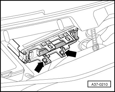
Installing control unit

Installation is performed in the reverse order.

  • ‒ → Locate multi-pin connector on control unit -J217- pins (arrows) then lock multi-pin connector.
  • ‒ Performing self-diagnosis => Page 01-21 .
  • ‒ Initiating basic setting => Page 01-46 .

Performing self-diagnosis > < Self-diagnosis - Guide