volkswagen Workshop Repair Guides

Volkswagen Workshop Service and Repair Manuals

Adjusting bevel gear (with stub shaft) > < Recommended sequence for new adjustment of final drive gear set
Adjusting shaft bevel gear
   
Adjusting shaft bevel gear
Special tools and workshop equipment required
t  Support plate -VW 309-
t  Universal measuring tool -VW 385-
t  Gearbox support -T10108-
t  Assembly tool -T10114-
t  Torque wrench -V.A.G 1332-
t  Dial gauge
t  Torque gauge, 0...600 Ncm, commercially available

Readjustment of the shaft bevel gear is required if
t  Pinion housing
t  Rear final drive housing
t  Tapered roller bearing for shaft bevel gear
or the
t  Final drive gear set
is renewed.
Adjustment overview → Chapter
Adjusting friction torque.
–  Screw on 12-point nut for shaft bevel gear.
   
–  Tighten 12-point nut to 120 Nm, measure friction torque and if necessary increase tightening torque until specified friction torque is attained.
A - 3/4” drive ratchet
–  Turn torque wrench -V.A.G 1332- to right to tighten.
–  Use 1/2” to 3/4” adapter.
  Note
Increase torque setting slowly and check friction torque at regular intervals. If the prescribed friction torque is exceeded, the spacer sleeve must be renewed and the adjustment repeated. A spacer sleeve which has been compressed too much cannot be reused.
Following friction torques are to be set:
  N39-1063
New bearingsUsed bearings → Note
200 ... 250 Ncm30 ... 50 Ncm

1)  run for at least 50 km (30 miles)
   
–  Measure friction torque.
-A- Torque gauge, 0 … 600 Ncm, commercially available
-B-1/2” to 3/4” adapter.
Determine thickness of shim "S3".
–  Install pinion housing complete with shaft bevel gear and temporary shim S3* (1.3 mm thick).
  Note
As a test prerequisite, a temporary shim S3 of 1.30 mm must be installed. It is referred to below as S3. After measured value “e” is determined, S3* is replaced with final shim S3.
–  Do not insert O-ring.
  N39-1059
–  Adjust setting ring of universal measuring tool -VW 385/1- to dimension a = 38 mm.
–  Set sliding positioning ring to dimension b = 35 mm.
  V39-0822
–  Set up universal mandrel according to figure. Measuring gauge extension -VW 385/16- = 12.3 mm. Set master gauge -VW 385/30- to Ro = 42.70 mm.
–  Set dial gauge to “0” with 2 mm preload.
–  After removing universal gauge, push on -VW 385/39- to stop.
  N39-0154
–  Place end measurement plate on head of shaft bevel gear.
  N39-0145
–  Insert universal mandrel.
–  Fit cover and tighten hexagon bolts.
–  Use sliding setting ring to pull centring disc outwards until mandrel can still just be turned by hand.
  N39-1033
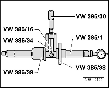
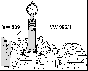
–  Determine dimension “e”. Turn test gauge until point of dial gauge makes contact with end measuring plate and indicates max. deflection (return point). The measured value is dimension “e” (in black scale). Example: 0.28 mm
–  Remove universal test gauge.
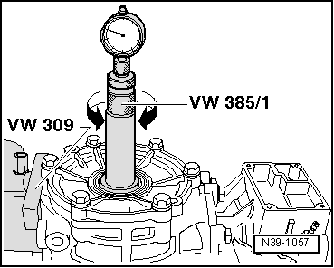
  Note
Finally, check again whether dial gauge returns to “0” with 2 mm preload with master gauge -VW 385/30- applied. Otherwise repeat measurement.
Determine thickness of shim "S3".
S3 = S3* + r + e
(“e” in black scale)
S3 = S3* + r - e
(“e” in red scale)
  Note
t  If measurement is obtained on red scale, subtract value “e”.
t  If measurement is obtained on black scale, add value “e”.
t  Allowance “r”, relative to master gauge “Ro” must be calculated according to the following formula.
Formula: r = R - Ro
R -  value written on bevel gear (in example, 43.14 mm).
 - Length of master gauge used
r = 43.14 mm - 42.70 mm
r = 0.44 mm
Example:
  N39-1057
Value indicated on dial gauge “e”0.28 mm
Calculated allowance “r” for this gear set0.44 mm
Installed shim S3*1.30 mm
Shim thickness "S3"= 2.02 mm

  Note
Allocate shims using → ETKA (electronic parts catalogue).
Available shims for S3
   
Shim thickness (mm)
1.301.692.08
1.331.722.11
1.361.752.14
1.391.782.17
1.421.812.20
1.451.842.23
1.481.872.26
1.511.902.29
1.541.932.32
1.571.962.35
1.601.992.38
1.632.022.41
1.662.052.44

–  Remove pinion housing complete with shaft bevel gear and 1.3 mm shim.
–  Install determined shim S3.
Two shims which total the measured value may be installed.
Carry out check measurement - check dimension “r”.
Insert universal test gauge and measure dimension “r”.
If the correct shims have been selected, the dial gauge, read anti-clockwise on the red scale, must now indicate the calculated allowance “r” within a tolerance of +0.04 mm.
   

Adjusting bevel gear (with stub shaft) > < Recommended sequence for new adjustment of final drive gear set