
Golf Mk4
| Assembly overview - repairing propshaft |
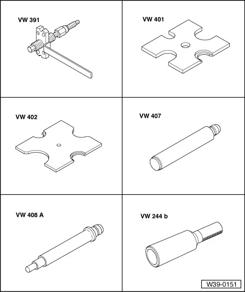
| Special tools and workshop equipment required |
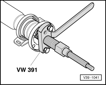
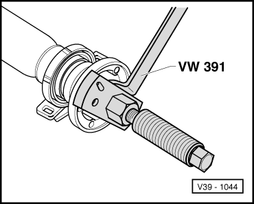
| t | Drive shaft fitting appliance -VW 391- |
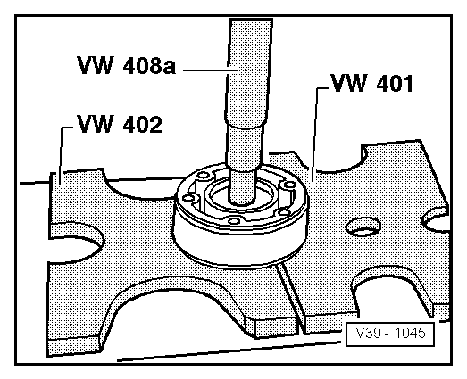
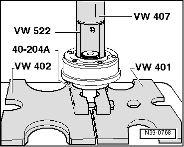
| t | Pressure plate -VW 401- |
| t | Pressure plate -VW 402- |
| t | Press tool -VW 407- |
| t | Press tool -VW 408A- |
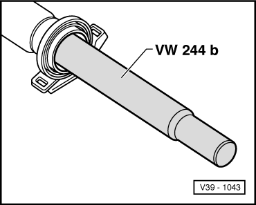
| t | Drift sleeve -VW 244B- |
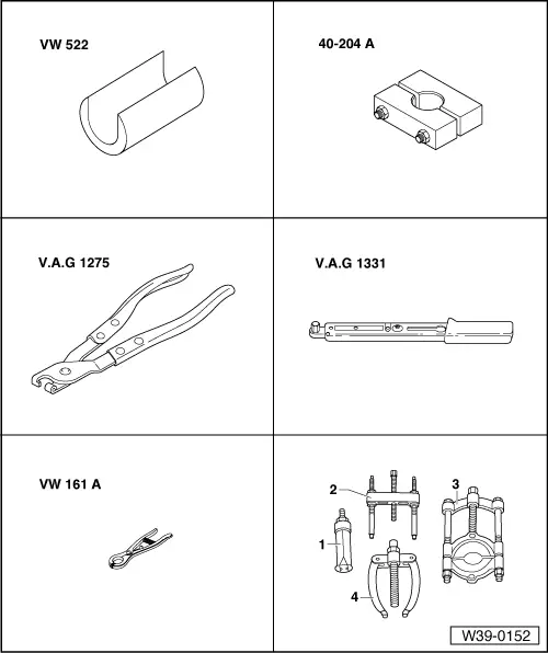
| t | Support sleeve -VW 522- |
| t | Tensioner -40 - 204 A- |
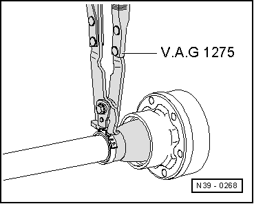
| t | Hose clip pliers -V.A.G 1275/- |
| t | Torque wrench -V.A.G 1331/- |
| t | Circlip pliers -VW 161 A- |
| t | Puller -2 - Kukko 18/0- |
| t | Splitter -3 - Kukko 17/1- |
 Note
Note
|
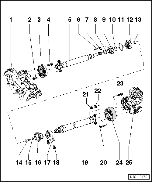
| 1 - | Gearbox with bevel box |
| 2 - | 12-point flange bolt, 60 Nm |
| 3 - | Flexible coupling with heat shield |
| q | Removing and installing → Chapter |
| q | Installation position → Fig. |
| 4 - | 12-point flange bolt, 60 Nm |
| 5 - | Front propshaft tube |
| q | Do not damage centring sleeve or seal inside flange when removing and installing. |
| 6 - | Socket head bolt, 40 Nm |
| 7 - | Locking plate |
| 8 - | Clamp |
| q | Tightening → Fig. |
| 9 - | Constant velocity joint boot |
| q | Drive off with a drift before pressing off constant velocity joint |
| q | Check for damage |
| 10 - | Dished washer |
| q | Inner circumference serrated. |
| q | Installation position: Large diameter lies against constant velocity joint. |
| 11 - | Seal |
| q | Renewing: pull off protective foil and stick onto joint. |
| 12 - | Constant velocity joint |
| q | Pressing off → Fig. |
| q | Pressing on → Fig. |
| q | Filling with grease: press 25 g grease -G6.3- into joint from each side (50 g total). Add grease if necessary when renewing joint boot. |
| 13 - | Retaining ring |
| q | Renew |
| q | Remove and install with circlip pliers -VW 161A-. |
| 14 - | Hexagon bolt, 45 Nm |
| 15 - | Washer |
| q | Always renew |
| 16 - | Flange |
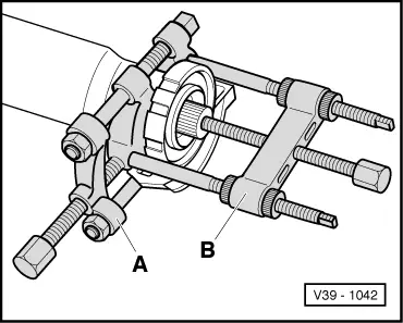
| q | Pulling off → Fig. |
| q | Pulling on → Fig. |
| 17 - | Intermediate bearing |
| q | Pulling off → Fig. |
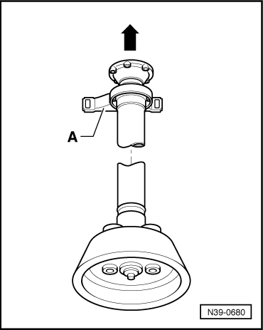
| q | Installation position → Fig. |
| q | Driving on → Fig. |
| 18 - | Bolt, 25 Nm |
| 19 - | Rear propshaft tube |
| q | Do not damage centring sleeve or seal inside flange when removing and installing. |
| 20 - | 12-point flange bolt, 60 Nm |
| q | Modification: from 06.99, new securing bolts with 12-point socket heads. |
| q | Two of the new securing bolts might be installed with balancing discs instead of washers. |
| q | Balancing washers on bolts have been discontinued with introduction of balancing nuts → Item and balancing washers → Item on bolts → Item. |
| 21 - | Balancing nut |
| q | Not fitted on all propshafts. |
| q | If flange bolt → Item is loosened, balancing nut and balancing washer → Item must not be reinstalled. |
| 22 - | Balancing washer |
| q | Not fitted on all propshafts. |
| q | If flange bolt → Item is loosened, balancing nut and balancing washer → Item must not be reinstalled. |
| 23 - | 12-point flange bolt, 60 Nm |
| q | Modification: From 09.02 onwards, new securing bolts with balancing nuts → Item and balancing washers → Item were introduced for some propshafts |
| q | Two of the new securing bolts might be installed with a balancing nut and balancing washer. |
| q | If securing bolts are unscrewed, balancing washer and balancing nut are not allowed to be reinstalled |
Note| Balancing washers in conjunction with bolt → Item are not installed then. |
| 24 - | Flexible coupling with vibration damper |
| q | Removing and installing → Chapter |
| q | Installation position → Fig. |
| 25 - | Rear final drive |
|
|
|
|
|
|
|
|
|
|
|
|
|
|