
Golf Mk4
| Dismantling and assembling selector forks |

| Special tools and workshop equipment required |
| t | Pressure plate -VW 402- |
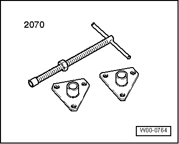
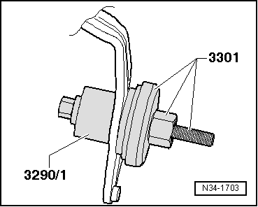
| t | Thrust piece -3290/1- from assembly tool -3290- |
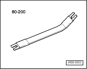
| t | Assembly tool -3301- |
| t | Thrust piece -VW 431- |
| t | Spacer sleeve -VW 472/2- |
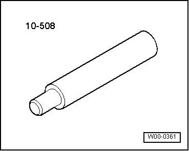
| t | Drift -10 - 206- |
|
|
|
|
|
|
 Note
Note
|
|

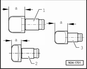
| 1 - | 5th gear selector segment |
| q | Identification → Fig. |
| q | After lock washer is installed, selector segment must still rotate freely. |
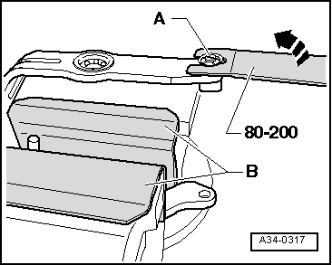
| 2 - | Lock washer |
| q | Always renew |
| q | Removing → Fig. |
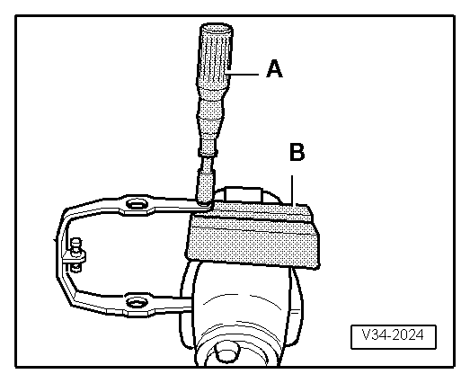
| q | Installing → Fig. |
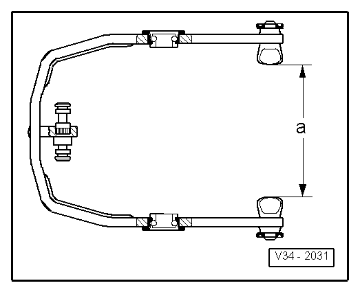
| 3 - | 5th gear selector fork |
| q | Adjusting → Anchor |
| 4 - | Bolt, 25 Nm |
| 5 - | 5th gear selector jaw |
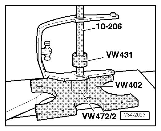
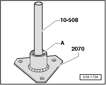
| 6 - | Angular contact ball bearing |
| q | Qty. 4 |
| q | Removing → Fig. |
| q | Press inner race into outer race → Fig. |
| q | Installing → Fig. |
| 7 - | Selector fork group with selector plate |
| 8 - | 1st/2nd gear selector segment |
| q | Identification → Fig. |
| q | After lock washer is installed, segment must still rotate freely |
| 9 - | Selector segment for 3rd and 4th gear |
| q | Identification → Fig. |
| q | After lock washer is installed, segment must still rotate freely |
| 10 - | Sliding piece |
| 11 - | Spring |
| 12 - | Selector fork for reverse gear |
| 13 - | Support for reverse gear selector fork |
| 14 - | Retaining ring |
| 15 - |
|
|
Note
|
|
Note
|
|
|
|
|
|
|
|
| Dim. -a- (mm) | |
| 1st/2nd gear selector fork | 87,2 ... 87,9 |
| 1st/2nd gear selector forks in conjunction with modified synchronisation | 88,4 ... 89,1 |
| 3rd/4th gear selector fork | 96,0 ... 96,7 |
|