
Golf Mk4
| Overview of electrical and electronic components and their locations |
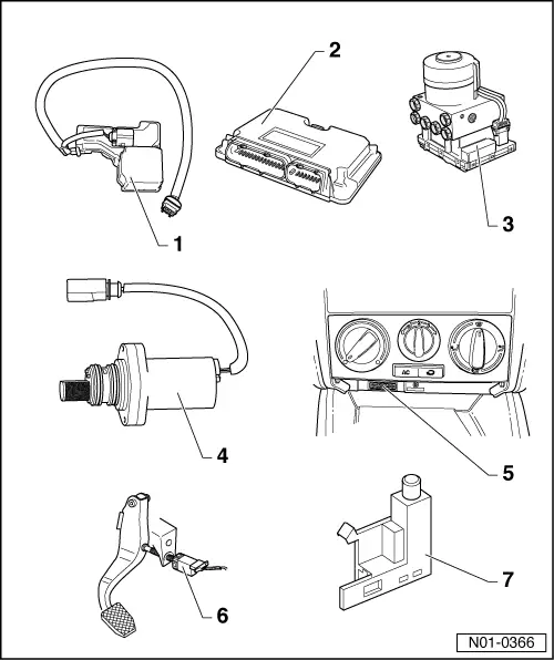
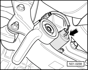
| 1 - | All-wheel drive control unit -J492- |
| q | Location → Fig. |
| q | Forms a unit together with oil pressure control motor -V184- and hydraulic temperature sender -G271-. |
| q | Overview - control units → Anchor. |
| q | Removing and installing → Chapter |
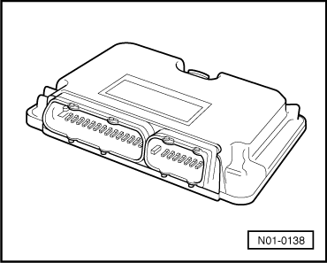
| 2 - | Engine control unit |
| q | Location → Fig. |
| q | The following signals are transmitted to the four-wheel drive control unit -J492- via the data bus: |
| q | Engine speed |
| q | Accelerator pedal position |
| q | Engine torque |
| q | Removing and installing → Rep. Gr.23 or → Rep. Gr.24 |
| 3 - | ABS control unit -J104- |
| q | Location: on hydraulic unit, on left in engine compartment |
| q | The following signals are transmitted to the four-wheel drive control unit -J492- via the data bus: |
| q | Rotational speeds of wheels |
| q | Longitudinal acceleration |
| q | Brake actuation |
| q | Removing and installing → Brake system; Rep. Gr.45 |
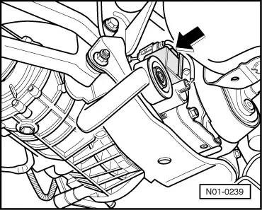
| 4 - | Haldex coupling pump -V181- |
| q | Location → Fig. |
| q | Can be checked using “guided fault finding” of -VAS 5051- |
| q | Removing and installing → Chapter |
| 5 - | Diagnostic connection |
| q | Location: in centre console below operating control unit for heating and air conditioning. |
| 6 - | Brake light switch -F- |
| q | Location: on brake pedal |
| q | Can be checked using “guided fault finding” of -VAS 5051- |
| q | Removing and installing → Brake systems; Rep. Gr.46. |
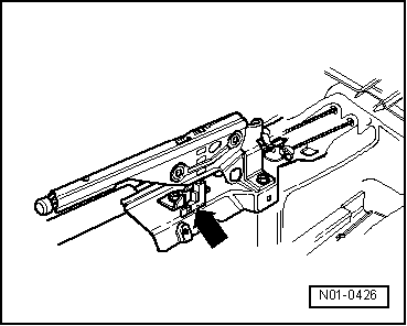
| 7 - | Handbrake warning switch -F9- |
| q | Location → Fig. |
| q | Can be checked using “guided fault finding” of -VAS 5051- |
| q | Removing and installing → Brake systems; Rep. Gr.46 |
|
|
|
|
|
|
|
|