volkswagen Workshop Repair Guides

Volkswagen Workshop Service and Repair Manuals

Checking gear oil in manual gearbox with bevel box > < Specified torques
Removing and installing bevel box
Special tools and workshop equipment required
   
t  Socket -V.A.G 1669-
  W00-0721
t  Torque wrench -V.A.G 1332-
t  Drip tray
Additional required information
t  Workshop Manual Golf 1998 ►, Bora 1999 ► Engine, mechanics
t  Workshop Manual Golf 1998 ►, Bora 1999 ►, Running gear, axles, steering - front and four-wheel drive
Removing
–  Mark position of propshaft with flexible coupling relative to bevel box flange.
  W00-0428
–  Unbolt propshaft with flexible coupling from bevel box flange -arrows-.
–  Disconnect right drive shaft from gearbox.
–  Raise drive shaft as high as possible and secure. Take care not to damage paint on drive shaft in the process.
–  If a cap is fitted, remove it by piercing cap centre with a screwdriver and levering out.
–  Remove right output shaft bolt or right flange shaft bolt using socket -V.A.G 1669- or commercially available 6 mm socket.
–  Separate exhaust system at double clamp → Rep. Gr.26.
  V34-2101
–  Remove pendulum support from subframe -arrows A-.
–  Carefully press engine and gearbox forwards.
–  Carefully pull front propshaft off centring pin.
  Note
Do not damage seal in the propshaft flange during removal or installation.
–  Place drip tray under gearbox and engine.
  N34-0887
–  Unbolt turbocharger oil return line -arrow- from engine → Rep. Gr.21.
–  Drain gear oil from bevel box.
  N34-0899
–  Remove bevel box carrier from engine and bevel box -arrows-.
–  Remove bevel box/gearbox connecting bolts.
–  Press bevel box off gearbox.
–  Remove bevel box.
Installing
Install in the reverse order of removal, observing the following:
  Note
  V34-2099
t  
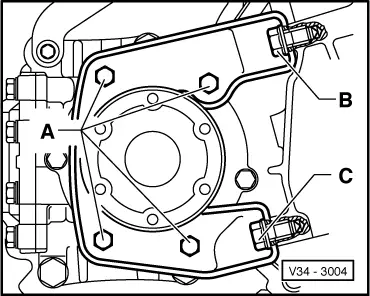
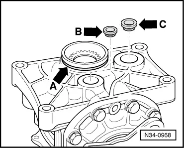
Always renew O-ring for sealing bevel box and gearbox -arrow A- and oil seals for sealing holes for oil supply system -arrows B and C-, lightly coating with oil.
t  Push bevel box completely onto gearbox, ensuring that splines of bevel box input shaft are guided centrally onto differential connecting piece.
t  Also bring splines of right flange shaft or drive flange with output shaft into alignment.
t  If the position of the splines and the centre guide are correct, then the bevel box will slide on to stop against the gearbox. Turn left drive shaft slightly if necessary.
t  Do not use securing bolts to pull bevel box onto gearbox, or bevel box will cant and bolt holes can break off.
t  When removing and installing, do not damage seals in propshaft flanges.
t  Renew propshaft if damaged.
t  Ensure that propshaft is horizontal when pushing onto centring pin.
t  Renew seal for drive shaft, if present → Running gear, axles, steering - front and four-wheel drive; Rep. Gr.40.
t  Join exhaust pipe at double clamp → Rep. Gr.26.
t  
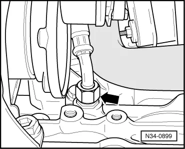
Unbolt turbocharger oil return line from engine → Rep. Gr.21.
t  Checking gear oil in manual gearbox with bevel box → Chapter.
Installing bevel box/engine carrier free of tension.
  N34-0968
When installing bevel box carrier, observe following sequence:
–  Screw in all bolts hand-tight.
–  Tighten bolts -B- and -C- first to 10 Nm.
–  Tighten bolts -A- to 25 Nm.
–  Tighten bolts -B- and -C- to 40 Nm.
Torque settings
  V34-3004
Bevel box to gearbox40 Nm + 45°

Flexible joint with heat shield to bevel box flange → Item.
Drive shaft to flange shaft → Running gear, axles, steering - front and four-wheel drive; Rep. Gr.40.
   

Checking gear oil in manual gearbox with bevel box > < Specified torques