
Golf Mk4
|
|
|
|
|
|
|
|
|
|
|
|
|
|
|
 Note
Note
|
|
Note
|
|
Note
|
|
|
|
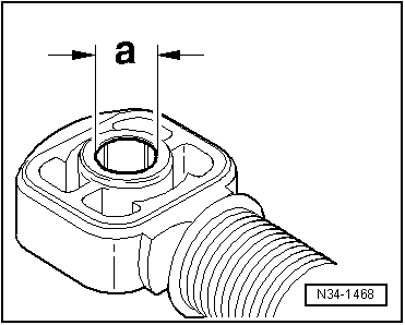
| Cable end-piece for | Dimension “a” |
| Gear selector cable to gearbox selector lever | 10 mm |
| Gate selector cable to relay lever | 8 mm |
|
|
|