
Golf Mk4
| Assembly overview - output shaft |
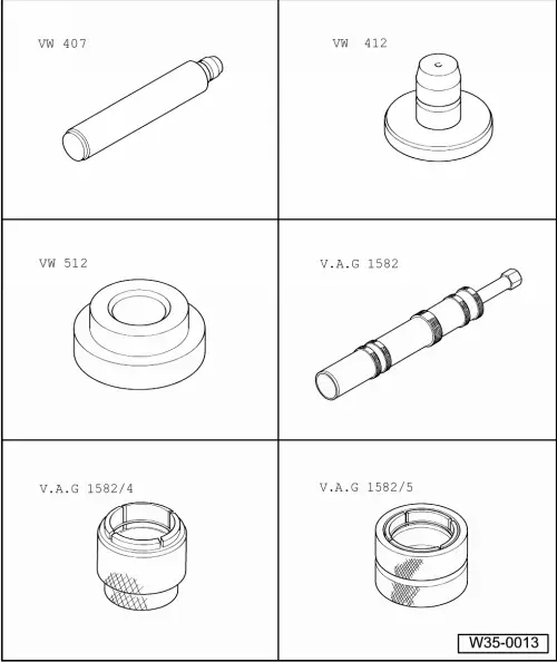
| Special tools and workshop equipment required |
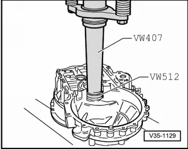
| t | Press tool -VW 407- |
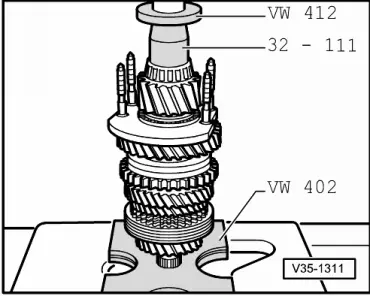
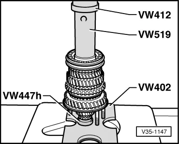
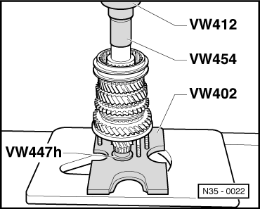
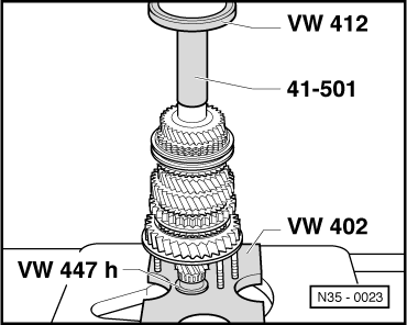
| t | Press tool -VW 412- |
| t | Thrust pad -VW 512- |
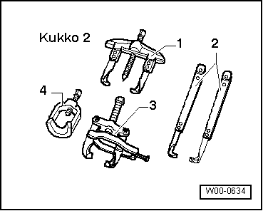
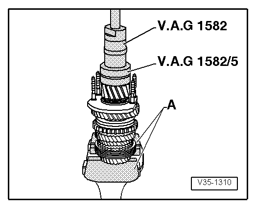
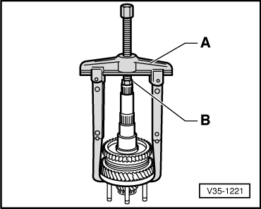
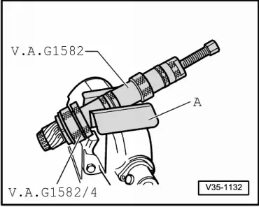
| t | Puller -V.A.G 1582- |
| t | Adapter -V.A.G 1582/4- |
| t | Adapter -V.A.G 1582/5- |
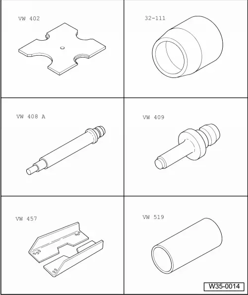
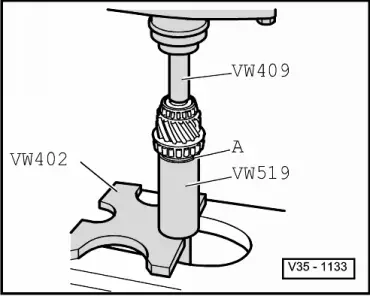
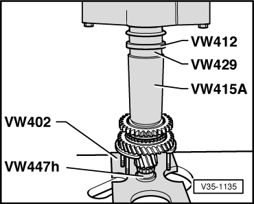
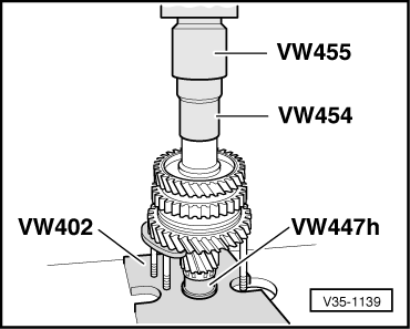
| t | Pressure plate -VW 402- |
| t | Thrust piece -32 - 111- |
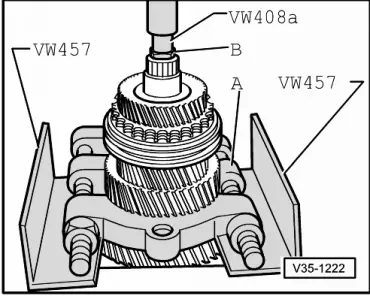
| t | Press tool -VW 408 A- |
| t | Press tool -VW 409- |
| t | Support rails -VW 457- |
| t | Tube -VW 519- |
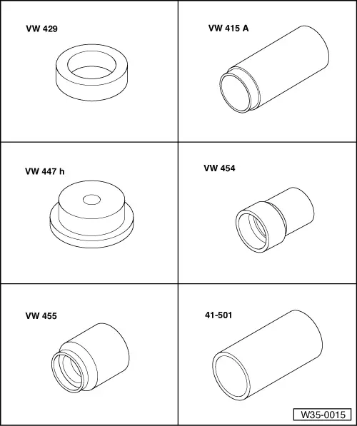
| t | Thrust ring -VW 429- |
| t | Tube -VW 415 A- |
| t | Thrust pad -VW 447 H- |
| t | Thrust piece -VW 454- |
| t | Installing sleeve -VW 455- |
| t | Drift sleeve - 41 - 501- |
|
|
|
|
 Note
Note
Note
|
|
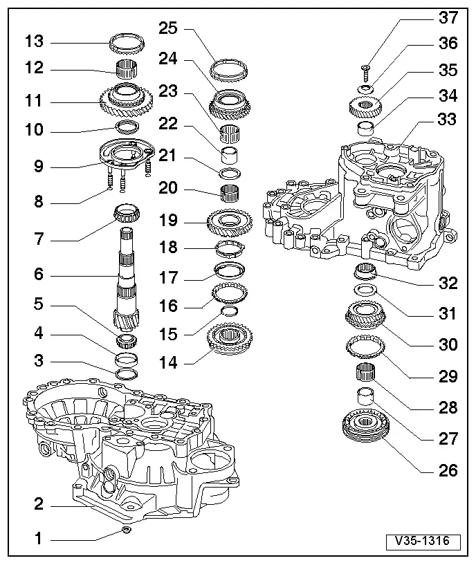
| 1 - | Hexagon nut |
| q | → Item |
| 2 - | Clutch housing |
| 3 - | Shim |
| q | Determining thickness → Chapter |
| 4 - | Small tapered roller bearing outer race |
| q | Removing → Fig. |
| q | Pressing in → Fig. |
| 5 - | Small tapered roller bearing inner race |
| q | Pulling off → Fig. |
| q | Pressing on → Fig. |
| 6 - | Output shaft |
| q | Paired with final drive gear wheel. Always renew as a set. |
| q | Adjusting → Chapter |
| 7 - | Large tapered roller bearing inner race |
| q | Pulling off → Fig. |
| q | Pressing on → Fig. |
| 8 - | Seal |
| q | Always renew |
| q | Place sealing rings (Qty. 4) on bearing support bolts |
| 9 - | Bearing support |
| q | With large tapered roller bearing outer race and bolts |
| q | Change outer race only together with large tapered roller bearing and bearing support |
| 10 - | Thrust washer |
| q | Shoulder of thrust washer faces tapered roller bearing |
| 11 - | Synchromeshed gear for 1st gear |
| q | From gearbox date 04 09 0 onwards, 1st gear synchronisation was changed → Chapter |
| 12 - | Needle bearing |
| q | For 1st gear |
| 13 - | Synchro-ring for 1st gear |
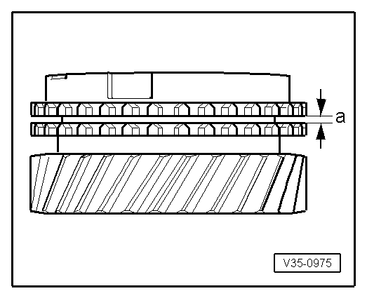
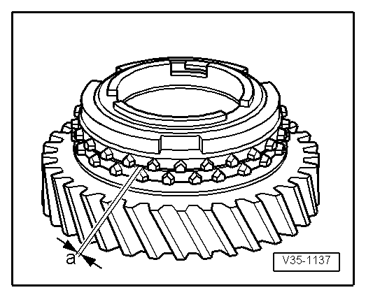
| q | Check for wear → Fig. |
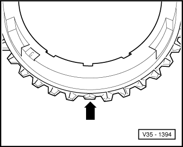
| q | Identification → Fig. |
| q | Distinguishing → Fig. |
| q | From gearbox date 04 09 0 onwards, 1st gear synchronisation was changed → Chapter |
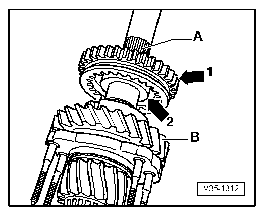
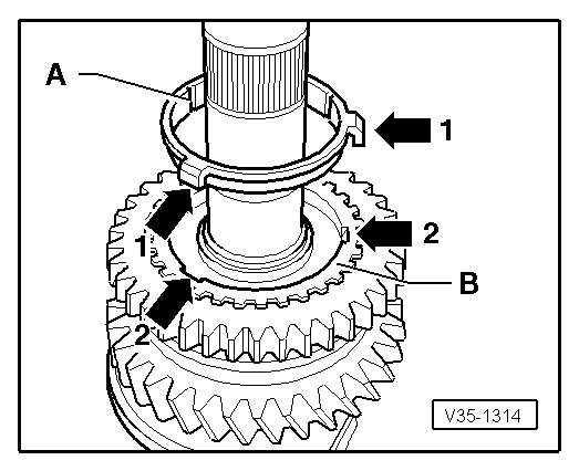
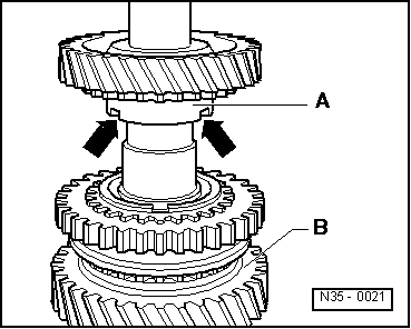
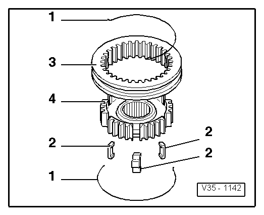
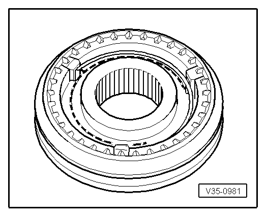
| 14 - | Locking collar with synchro-hub for 1st and 2nd gears |
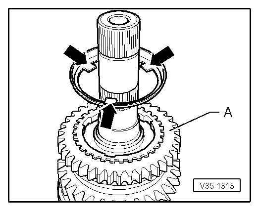
| q | After removing retaining ring → Item, pull off via bearing support → Fig. |
| q | Dismantling → Fig. |
| q | Assembling locking collar and synchro-hub → Fig. |
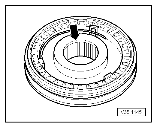
| q | Installation position → Fig. |
| q | Pressing on → Fig. |
| q | From gearbox date 04 09 0 onwards, 1st gear synchronisation was changed → Chapter |
| 15 - | Retaining ring |
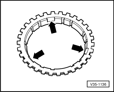
| 16 - | Synchro-ring for 2nd gear |
| q | Identification → Fig. |
| q | Distinguishing → Fig. |
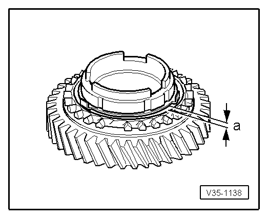
| q | Check for wear → Fig. |
| q | Assemble so that notches engage in locking pieces of locking collar → Item |
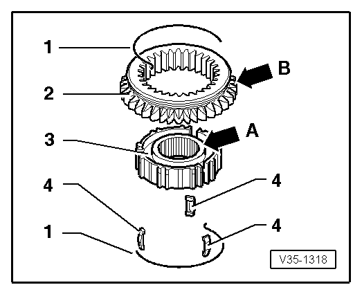
| 17 - | Outer ring |
| q | Insert in synchro-ring → Item; installation position → Fig. |
| q | Renew if scored |
| 18 - | Synchro-ring |
| q | (Inner ring) |
| q | Check for wear → Fig. |
| q | Check lugs for scoring |
| q | Installation position → Fig. |
| 19 - | Synchromeshed gear for 2nd gear |
| q | Installation position → Fig. |
| 20 - | Needle bearing |
| q | For 2nd gear |
| 21 - | Thrust washer |
| 22 - | Sleeve for 3rd gear needle bearing. |
| q | Pressing off with synchromeshed gear for 2nd gear → Fig. |
| q | Pressing on → Fig. |
| 23 - | Needle bearing |
| q | For 3rd gear |
| 24 - | Synchromeshed gear for 3rd gear |
| 25 - | Synchro-ring for 3rd gear |
| q | Check for wear → Fig. |
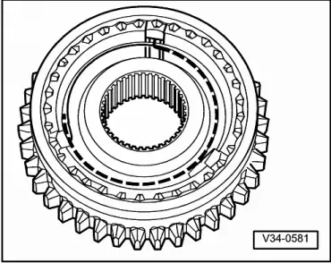
| 26 - | Locking collar with synchro-hub for 3rd and 4th gears |
| q | Press off with 2nd gear synchromeshed gear → Item and 3rd gear → Item → Fig.. |
| q | Dismantling → Fig. |
| q | Installation position, locking collar and synchro-hub → Fig. |
| q | Assembling locking collar and synchro-hub → Fig. |
| q | Pressing on → Fig. |
| 27 - | Sleeve |
| q | For needle bearing |
| q | Press off with locking collar and synchro-hub for 3rd and 4th gears → Item |
| q | Pressing on → Fig. |
| 28 - | Needle bearing |
| q | For 4th gear |
| 29 - | Synchro-ring for 4th gear |
| q | Check for wear → Fig. |
| 30 - | Synchromeshed gear for 4th gear |
| 31 - | Thrust washer |
| 32 - | Needle bearing |
| q | For output shaft |
| q | Removing and installing → Chapter |
| 33 - | Gearbox housing |
| 34 - | Sleeve |
| q | For output shaft needle roller bearing |
| q | Pressing off → Fig. |
| q | Pressing on → Fig. |
| 35 - | Gear wheel for 5th gear |
| q | Removing and installing → Chapter |
| 36 - | Dished washer |
| q | Installation position → Anchor |
| 37 - | Torx socket head bolt M10 |
| q | → Item |
|
|
|
|
|
|
|
|
Note
|
|
|
|
|
|
|
|
| Gap “a” | Installation (new) dimension | Wear limit |
| 1st gear 3rd gear 4th gear | 1.0 ... 1.7 mm 1.0 … 1.7 mm 1.0 … 1.7 mm | 0.5 mm |
|
|
|
|
|
|
|
|
|
|
Note
|
|
|
|
| Gap “a” | Installation (new) dimension | Wear limit |
| 2nd gear | 1.2 ... 1.8 mm | 0.5 mm |
|
|
|
|
| Gap “a” | Installation (new) dimension | Wear limit |
| 2nd gear | 0.75 ... 1.25 mm | 0.3 mm |
|
|
|
|
|
|
|
|
|
|
|
|
|
|
|
|
|
|