
Golf Mk4
|
Removing and installing gearbox
Removing and installing gearbox
|
 |
|
|
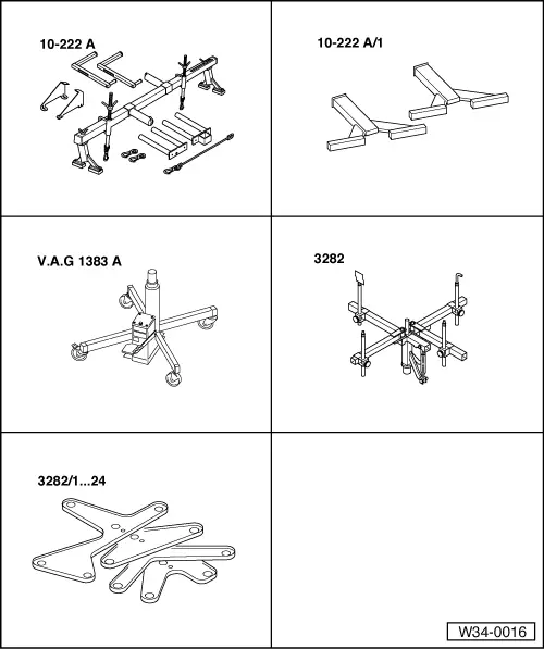
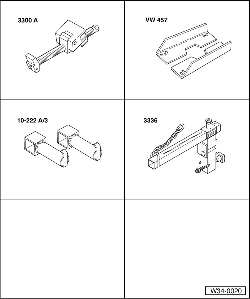
Special tools, workshop equipment, test and measuring appliances and auxiliary items required
Additionally for vehicles with 5 and 6-Cyl. engines
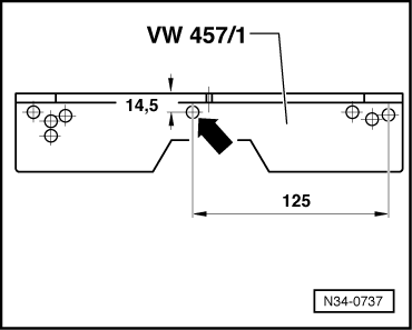
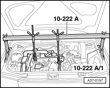
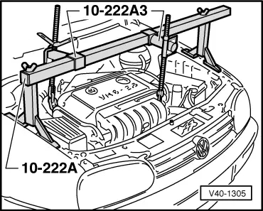
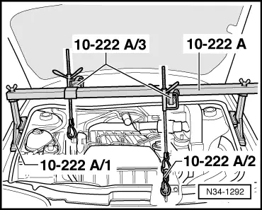
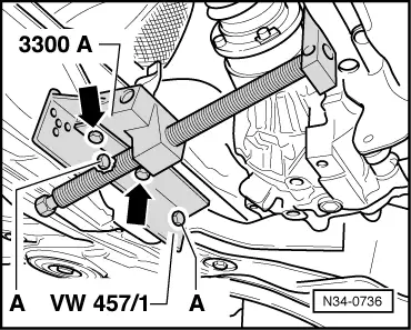
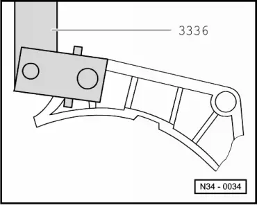
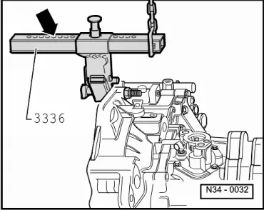
Modifying support rail VW 457/1 |
 |
|
→ To secure support rail VW 457/1 to the subframe a new hole is required. Dimensions given are in mm.
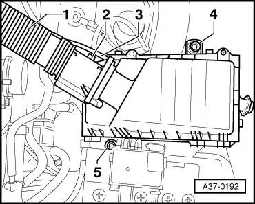
Removing |
 |
|
|
 |
|
|
Gearboxes up to 05.99
|
 |
|
|
 |
|
|
 |
|
Note: Do not depress clutch pedal. |
 |
|
Gearboxes from 05.99 |
|
|
|
 |
|
|
 |
|
|
|
|
Note: Do not depress clutch pedal. |
 |
|
|
 |
|
|
→ Continued for vehicles with 4-Cyl. engine
|
 |
|
|
→ Continued for vehicles with 5 and 6-Cyl. engines
|
 |
|
Continuation for all vehicles
=> Electrical system; Repair group 27; Starter motor; Removing and installing starter motor
|
 |
|
|
 |
|
=> Repair group 26; Removing and installing parts of the exhaust system.
|
 |
|
|
 |
|
|
 |
|
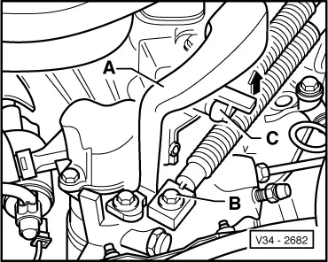
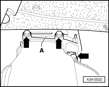
-A- Qty. 2 hexagon bolts M 8 x 25
|
 |
|
|
→ Vehicles with 5 valve engine
Continuation for all vehicles
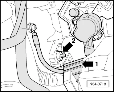
Note: Do not damage P.A.S. pipe when moving engine/gearbox assembly. |
 |
|
|
 |
|
|
 |
|
Note: Do not damage P.A.S pipe when lowering gearbox. |
 |
|
|
Transporting the gearbox
|
 |
|
|
Notes:
|
 |
|
|
|
|
|
The clutch plate must be able to slide lightly to and fro on the input shaft.
|
|
|
-A- Qty. 2 hexagon bolts M 8 x 25
→ Vehicles with 5 valve engine
Continuation for all vehicles
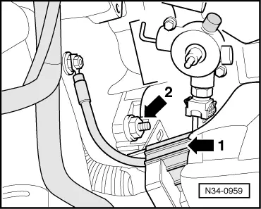
Note: Do not damage P.A.S pipe. |
 |
|
|
|
|
Note: Do not damage P.A.S pipe. |
|
|
|
|
|
|
|
|
Warning!
Do not remove support 10-222A until all bolts have been tightened to the prescribed torque setting. |
 |
|
=> Running gear, axles, steering; Repair group 40
=> Repair group 26; Removing and installing parts of the exhaust system.
|
 |
|
=> Running gear, Axles, Steering front and four-wheel drive; Repair group 40; Servicing drive shafts
=> Electrical system; Repair group 27; Starter motor; Removing and installing starter motor |
|
|
|
|
Gearboxes up to 05.99 |
|
|
|
 |
|
=> Repair group 24; Servicing injection system
Note: Note radio coding for vehicles with coded radio.
Gearboxes from 05.99 |
|
|
|
|
|
=> Repair group 24; Servicing injection system
Note: Note radio coding for vehicles with coded radio.
Tightening torques |
 |
|||||||||||||||||||||||||
|
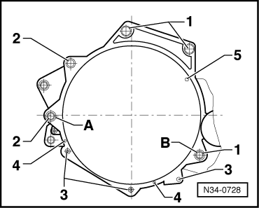
Gearbox to engine → Vehicles with 4-Cyl. engine
1) Also starter to gearbox 2) Only on engines with an aluminium sump, 3) Large cover plate for flywheel only on engines with heat steel sump (sump painted black) 4) Small cover plate for flywheel Items A + B - Dowel sleeves |
 |
|||||||||||||||||||||||||
|
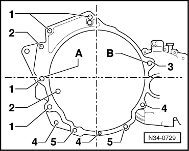
→ Vehicles with 5 and 6-Cyl. engine
1) Also starter to gearbox 2) Only on engines with an aluminium sump, on some engines M 10 x 50 bolts are fitted, the tightening torque is 25 Nm. 3) Flywheel cover plate only on engines with a sheet steel sump (sump painted black) Items A + B - Dowel sleeves Continuation for all vehicles |
|
|||
| |||
|
||||
|
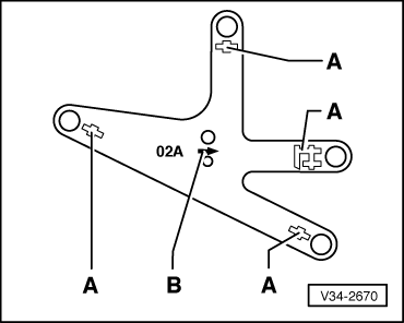
→ Gearbox to body
|
|
||||||||||||
|
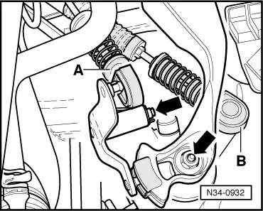
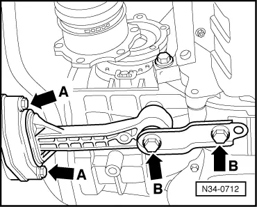
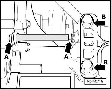
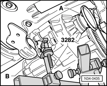
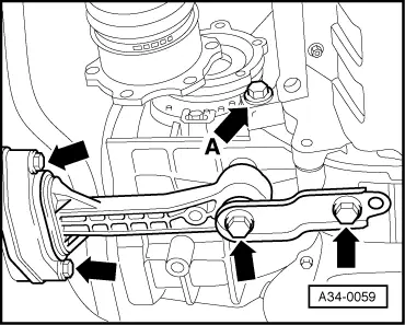
→ Rear gearbox mounting
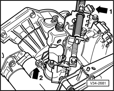
Pendulum support to subframe and gearbox (bolts -A- and -B-) => Running gear, axles, steering; Repair group 40 Note: Install engine/gearbox mountings stress-free. => Repair group 10; Removing and installing engine. Selector mechanisms up to 05.99 Selector cable support bracket to gearbox => page 34-5 , item 14
Selector mechanisms from 05.99 Selector cable support bracket to gearbox => page 34-41 , item 9
| ||||||||||||