
Golf Mk4
|
Servicing gearbox housing and clutch housing
Servicing gearbox housing and clutch housing
|

 |
|
|
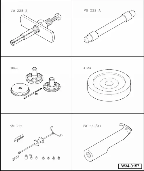
Special tools, workshop equipment, test and measuring appliances and auxiliary items required
Oil seal and sleeve are two parts:
Oil seal and sleeve are one part:
|
 |
|
|
Special tools, workshop equipment, testers, measuring instruments and auxiliary items required Oil seal and sleeve are one part:
|
 |
|
|
|
|
|
|
|
|
|
|
|
|
|
|
|
 |
|
|
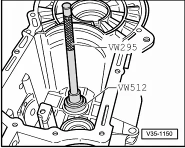
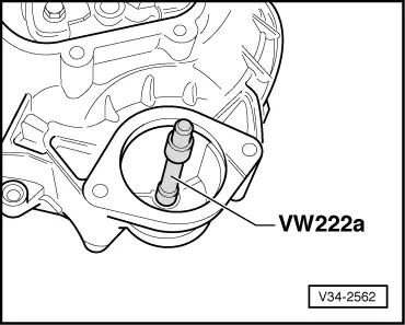
→ Fig.1 Knocking-out needle roller bearing. |
 |
|
|
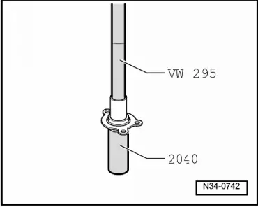
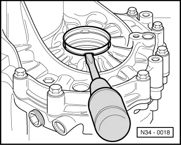
→ Fig.2 Knocking needle roller bearing in onto stop |
 |
|
|
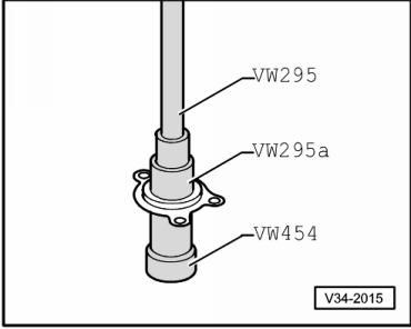
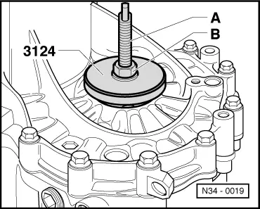
→ Fig.3 Knocking oil seal out of guide sleeve. |
 |
|
|
→ Fig.4 Knock oil seal into the guide sleeve onto stop. |
 |
|
|
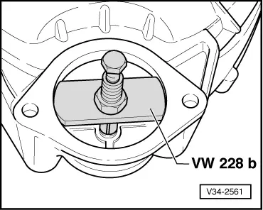
→ Fig.6 Knocking in starter bush. |
 |
|
|
→ Fig.7 Lever out sleeve with screwdriver |
 |
|
|
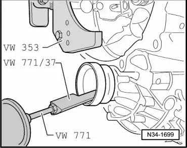
→ Fig.9 Pull out sleeve and oil seal A shoulder is located on the internal diameter of the sleeve
|
 |
||||||
|
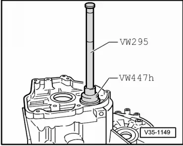
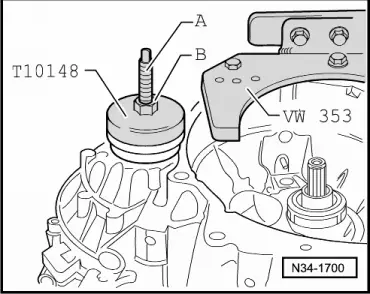
→ Fig.10 Pulling sleeve and seal in
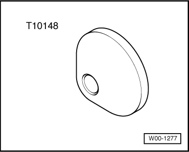
Note: When gearbox is dismantled press sleeve in onto stop with thrust piece T10148. | ||||||