
Golf Mk4
|
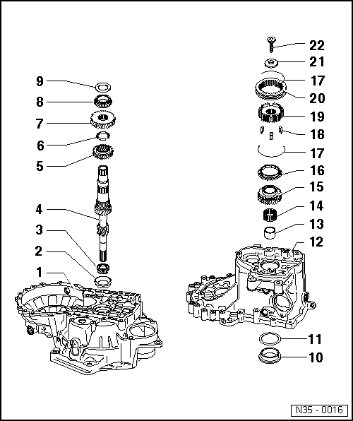
Dismantling and assembling input shaft
Dismantling and assembling input shaft
|
 |
|
|
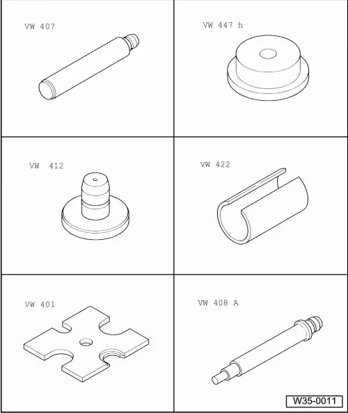
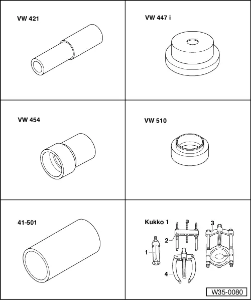
Special tools, workshop equipment, test and measuring appliances and auxiliary items required
|
 |
|
|
Notes:
|
|
|
|
|
|
|
|
|
|
|
|
 |
|
|
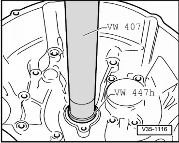
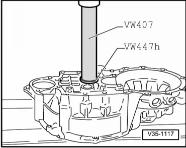
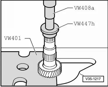
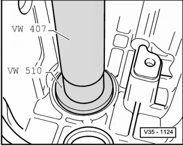
→ Fig.1 Pressing out taper roller bearing outer race |
 |
|
|
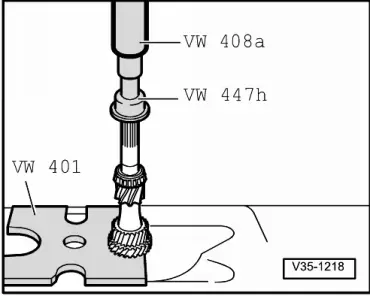
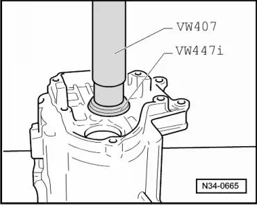
→ Fig.2 Pressing in taper roller bearing outer race |
 |
|
|
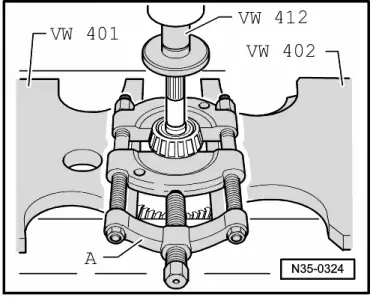
→ Fig.3 Pressing out taper roller bearing inner race A - Separating device Kukko 17/1 |
 |
|
|
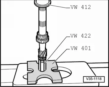
→ Fig.4 Pressing on taper roller bearing inner race |
 |
|
|
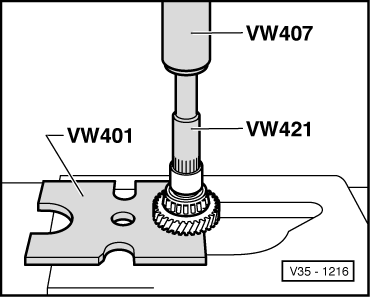
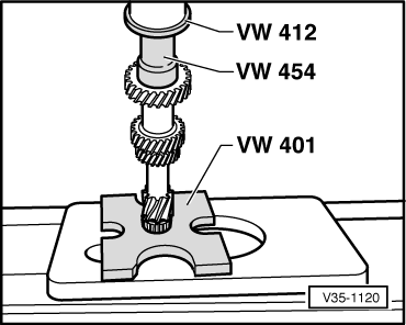
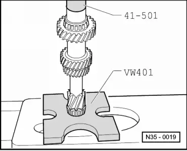
→ Fig.5 Pressing off 4th gear wheel with taper roller bearing and sleeve |
 |
|
|
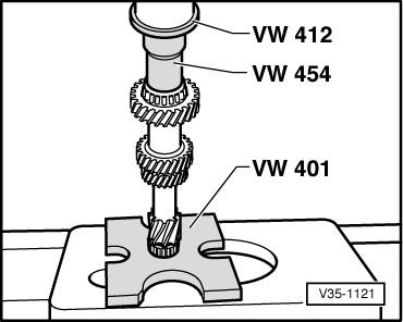
→ Fig.6 Pressing off 3rd gear wheel |
 |
|
|
→ Fig.7 Pressing on 3rd gear wheel |
 |
|
|
→ Fig.8 Pressing on 4th gear wheel Shoulder points to 3rd gear. |
 |
|
|
→ Fig.9 Pressing on taper roller bearing inner race |
 |
|
|
→ Fig.10 Pressing on sleeve for needle roller bearing |
 |
|
|
→ Fig.11 Pressing out taper roller bearing outer race |
 |
|
|
→ Fig.12 Pressing in taper roller bearing outer race |
 |
|
|
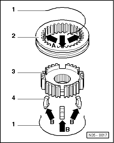
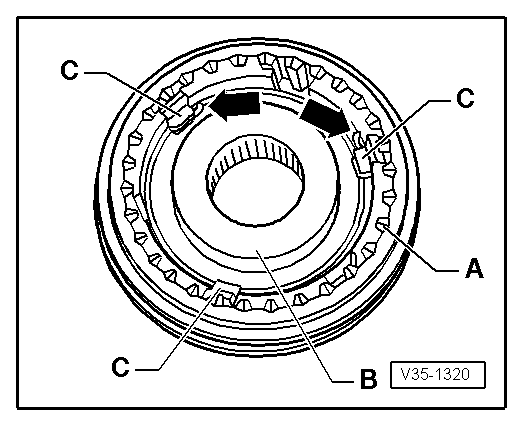
→ Fig.14 Assembling 5th gear locking collar/synchro-hub
Pointed teeth -A- and shoulder -B- of synchro-hub face in same direction. The recesses for the locking pieces in locking collar and synchro-hub must be aligned (Fig.13 ). |