
Golf Mk4
|
|
|
|
|
|
|
|
|
|
|
|
|
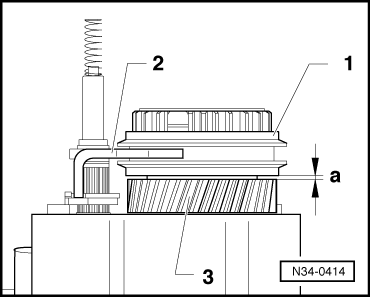
| Thickness (mm) | Identification |
| 2.5 | Brown |
| 2.6 | Black |
| 2.7 | Polished |
| 2.8 | Copper |
| 2.9 | Brass |
| 3.0 | Blue |
|
 Note
Note
|
|
|
|
|
|
Note
|
|
|
|
|
|
|
|
|
|
|
|
Note
|
|
|
|
Note
|
|
|
|
|
|
|
|
|
|
Note
|
|
|
|
Note
|
|
|
|
|
|