
Golf Mk4
|
Removing and installing gearbox
Removing and installing gearbox
|

 |
|
|
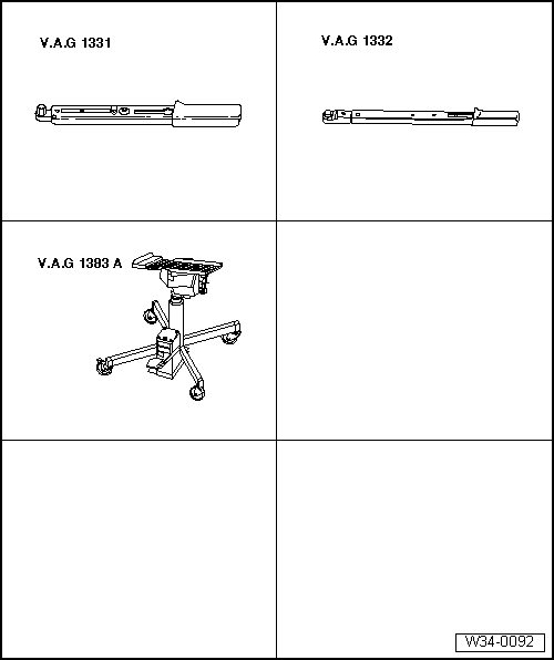
Special tools, workshop equipment, test and measuring appliances and auxiliary items required
Removing
=> Repair group 24; Servicing injection system; Removing and installing parts of injection system |
 |
|
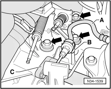
Remove relay lever and gear selector lever from gearbox as follows: |
 |
|
 |
|
|
 |
|
Note: Do not depress clutch pedal.
|
 |
|
|
 |
|
=> Electrical system; Repair group 27; Starter motor; Removing and installing starter motor
=> Repair group 26; Removing and installing parts of the exhaust system. |
 |
|
|
 |
|
|
 |
|
|
 |
|
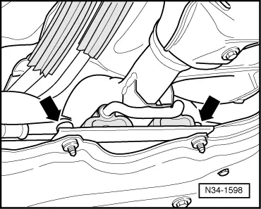
Note: Do not damage P.A.S pipe when lowering gearbox. |
 |
|
|
 |
|
|
 |
|
|
 |
|
Note: Do not damage P.A.S pipe when lowering gearbox. Transporting the gearbox |
 |
|
|
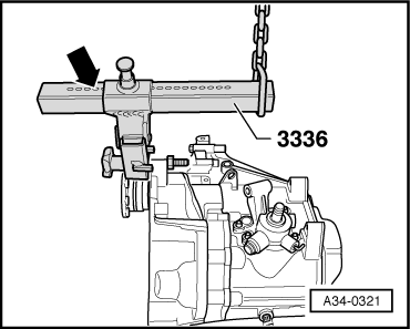
 |
|
|
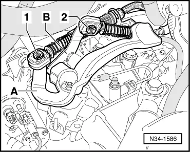
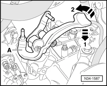
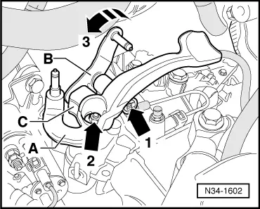
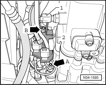
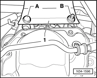
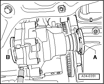
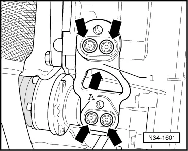
→ If the gearbox has been replaced,the bracket -1- for the pendulum support on clutch housing must always be transferred to new component. The curvature -arrow A- faces forwards. Torque settings for bolts -arrows- , item 6 .
The clutch plate must be able to slide lightly to and fro on the input shaft.
|
|
|
|
|
|
Note: Do not damage P.A.S pipe.
|
|
|
|
|
|
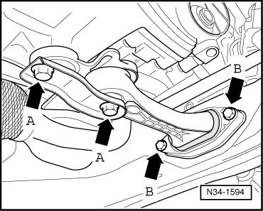
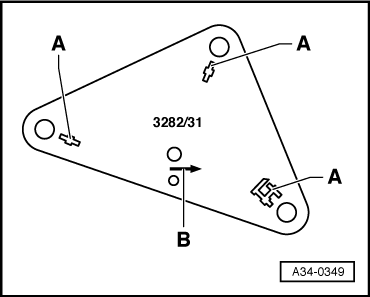
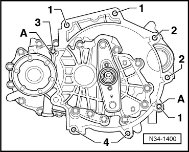
Note: Observe different length of securing bolts -A- and -B-.
|
|
|
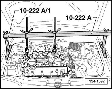
Warning!
Do not remove support bar 10-222A until the bolts securing the left-hand assembly mounting have been tightened to the prescribed torque setting.
|
|
|
|
|
|
|
|
|
=> Repair group 26; Removing and installing parts of the exhaust system.
=> Repair group 26; Removing and installing parts of the exhaust system.
=> Repair group 26; Removing and installing parts of the exhaust system.
=> Electrical system; Repair group 27; Starter motor; Removing and installing starter motor |
|
|
|
|
|
|
|
|
|
|
=> Repair group 24; Servicing injection system; Removing and installing parts of injection system
Note: Note radio coding for vehicles with coded radio.
Gear oil specification => Page 00-3
Tightening torques |
 |
|||||||||||||||||||||
|
→ Gearbox to engine
1) Also starter to gearbox Item A - Centring sleeves |
|
||||
|
→ Gearbox console -1- to gearbox
|
|
||
|
→ Gearbox to body
Note: Install engine/gearbox mountings stress-free. |