
Golf Mk4
|
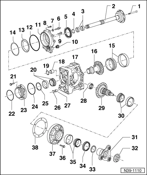
| 1 - | Countersunk bolt, 25 Nm |
| q | Right flange shaft to threaded piece of differential |
| q | Length of countersunk bolt is matched to bevel box. |
| q | Check part number of bevel box. |
| q | When renewing bevel box, allocate countersunk bolt with → Electronic parts catalogue (ETKA). |
| 2 - | Right flange shaft |
| q | Removing → Anchor |
| q | Pressing in → Fig. |
| q | Removing and installing with gearbox installed → Chapter. |
| 3 - | Needle bearing (polygon bearing) |
| q | Qty. 2 |
| q | Renewing → Chapter |
| 4 - | Retaining ring |
| q | Always renew |
| 5 - | Seal |
| q | Pry out with assembly lever |
| q | Drive in to stop with thrust piece -T10049- → Anchor |
| q | Renewing with gearbox installed → Chapter |
| 6 - | Centre hex stud, 45 Nm |
| q | M10/ M8 |
| 7 - | Washer |
| q | For centre hex stud → Item. |
| 8 - | Bolt, 25 Nm |
| q | M8 |
| 9 - | Bolt, 45 Nm |
| q | M10 |
| 10 - | Oil drain plug, 60 Nm |
| q | With magnet and seal |
| 11 - | Large cover → Remark |
| q | Removing → Anchor |
| q | Do not cant when installing. Tighten securing bolts diagonally and in stages |
| 12 - | O-ring |
| q | Always renew, if part of original equipment |
| 13 - | Oil deflector ring |
| q | Observe installation position → Anchor |
| q | Installed in some gearboxes between shim S1 → Item and large tapered roller bearing for supporting bevel gear with stub shaft → Item. |
| 14 - | Shim S1 |
| q | Note thickness |
| q | Installed in some gearboxes between oil deflector ring → Item and large cover → Item. |
| q | Adjustment overview → Chapter |
| 15 - | Large tapered roller bearing for supporting bevel gear with stub shaft → Remark |
| Inner race: |
| q | Pressing off → Anchor |
| q | Pressing on → Anchor |
| Outer race: |
| q | Pulling out → Anchor |
| q | Pressing in → Anchor |
| 16 - | Bevel gear with stub shaft → Remark |
| q | Paired with shaft bevel gear → Item. |
| q | Cannot be pressed off input shaft. |
| q | Adjusting → Chapter |
| 17 - | Final drive housing → Remark |
| q | Drain oil then and secure bevel box on assembly stand using gearbox support -T10108- → Chapter. |
| 18 - | Sleeve for oil supply |
| q | Pulling out → Anchor |
| q | Pressing in → Fig. |
| 19 - | O-ring |
| q | Always renew |
| 20 - | Small tapered roller bearing for supporting bevel gear with stub shaft → Remark |
| Inner race: |
| q | Sits loosely on input shaft |
| q | Removing → Anchor |
| q | Installing → Anchor |
| Outer race: |
| q | Sits loosely in final drive housing |
| q | Removing → Anchor |
| q | Installing → Anchor |
| 21 - | Bolt, 25 Nm |
| 22 - | O-ring |
| q | Always renew |
| q | Must lie in circumferential groove. |
| 23 - | Small cover → Remark |
| q | Removing → Anchor |
| q | Do not cant when installing. Tighten securing bolts diagonally and in stages |
| 24 - | O-ring |
| q | Always renew |
| 25 - | Shim S2 |
| q | Note thickness |
| q | Adjustment overview → Chapter |
| 26 - | O-ring |
| q | Always renew |
| 27 - | Sleeve for oil supply |
| q | Pulling out → Anchor |
| q | Pressing in → Fig. |
| 28 - | Roller sleeve |
| q | Pulling out → Anchor |
| q | Pressing in → Fig. |
| 29 - | Shaft bevel gear → Remark |
| q | Is paired to bevel gear (with stub shaft) |
| q | Clean thread |
| q | Lubricate splines for output flange with multi-purpose grease. |
| q | Adjusting → Chapter |
| 30 - | Large tapered roller bearing for shaft bevel gear → Remark |
| Inner race: |
| q | Set on shaft bevel gear → Item. |
| Outer race: |
| q | Pressing out → Anchor |
| q | Pressing in → Anchor |
| 31 - | Output flange → Remark |
| q | Pulling out → Anchor |
| q | Pulling in → Fig. |
| q | Lubricate splines with multi-purpose grease. |
| 32 - | Hexagon nut, 475 Nm |
| q | Unscrewing → Anchor |
| q | Fitting → Anchor |
| q | Always renew |
| q | Insert with locking fluid -D 000 600- |
| 33 - | Shim S4 |
| q | Note thickness |
| q | Adjustment overview → Chapter |
| q | Set on shaft bevel gear → Item before inserting small tapered roller bearing inner race → Item. |
| 34 - | Seal |
| q | Replace only with bevel box removed → Chapter |
| 35 - | Small tapered roller bearing for shaft bevel gear → Remark |
| Outer race: |
| q | Pressing out → Anchor |
| q | Pressing in → Anchor |
| Inner race: |
| q | Pull off output flange → Anchor. |
| q | Place in outer race. |
| 36 - | Bolt, 25 Nm |
| q | Insert with sealant -AMV 188 200-. |
| 37 - | Pinion housing → Remark |
| q | Removing → Anchor |
| q | Installing → Anchor |
| q | Do not cant when installing. Tighten securing bolts diagonally and in stages. |
| 38 - | Shim S3 |
| q | Note thickness |
| q | Adjustment overview → Chapter |
| q | Before installing, coat both sides with sealant -AMV 188 200-. |