volkswagen Workshop Repair Guides

Volkswagen Workshop Service and Repair Manuals

Differential for rear final drive > < Removing
Installing
Installing
   
–  First press plate housing out of Haldex coupling cover.
  N39-1016
–  Insert bevel gear with stub shaft.
–  Install left cover with new O-ring.
–  Moisten O-ring with gear oil.
–  Tighten hexagon bolts to specified torque → Item.
  N39-0102
–  Insert right cover with differential and new O-ring -A- (moistened with gear oil) and tighten bolts evenly and diagonally.
–  Tighten hexagon bolts to specified torque → Item.
–  Press breather into rear final drive housing.
  N39-0758
Use new retaining ring -A- to press old retaining out of groove in flange shaft.
–  Drive in left and right flange shafts with plastic hammer.
–  Install shim S3.
  V34-2005
–  Insert new O-ring -A- in circumferential groove of pinion housing and moisten with gear oil.
–  Install pinion housing with shaft bevel gear.
Installation position:
Oil filter mounting is located above oil filler plug.
–  Screw in hexagon nuts with locking fluid -D 197 300 A1- and tighten in stages diagonally to specified torque → Item.
  N39-0756
–  Lay washer -1- for needle thrust bearing in pinion housing with shoulder facing needle thrust bearing -2--arrow A-.
–  Then set needle thrust bearing -2- in place.
–  Then insert thrust washer -3- with larger smooth surface -arrow B- facing hub -4-.
–  Now push hub -4- onto shaft bevel gear with the 3 holes -arrow C- facing upwards.
  N39-1041
–  Lay first inner plate -2- in pinion housing -1-.
–  Then insert first outer plate -3- and then the remaining 6 inner and 6 outer plates.
  N39-1042
–  Ensure that cam track remains visible when cam disc -A- is installed.
Installation position:
The 3 shortened teeth -arrows- must engage in the mating teeth of the hub.
  N39-1046
–  Turn plate housing -A- while inserting it -arrows-, guiding housing onto cam disc and set of plates.
–  Lay the 3 rollers -B- in recesses of plate housing.
–  Also set the 6 wheel rollers -C- in plate housing.
  Note
The plate housing is shaped so that rollers and wheel rollers can only be fit in one position.
–  Then install ring -D-.
  N39-1043
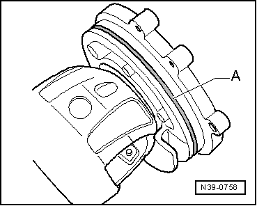
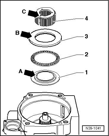
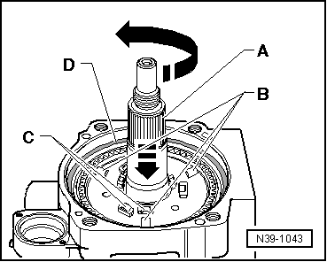
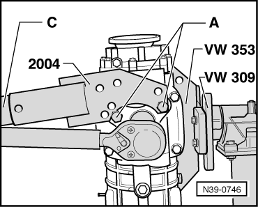
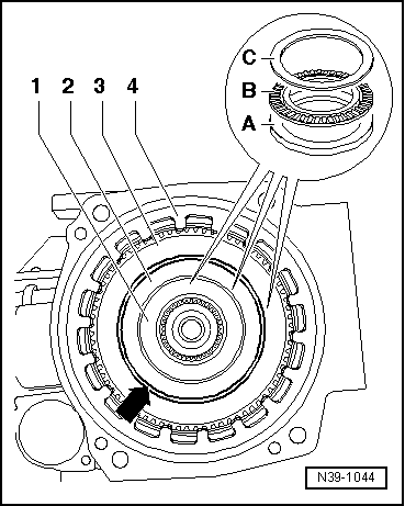
–  Lay thicker thrust washer -A- on wheel rollers and rollers in plate housing.
–  On top of that, lay needle thrust bearing -B- and thin thrust washer -C- for needle thrust bearing.
  Note
t  
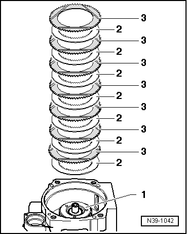
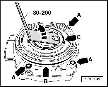
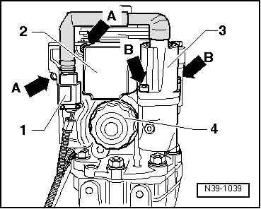
The individual needle thrust bearing packets 1 through 3 are allocated to the diameters of the pistons in Haldex coupling cover.
t  
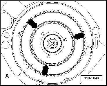
Ensure that gap -arrow- between needle thrust bearing packets 2 and 3 is of uniform size all around the circumference.
–  Insert dished spring -4- with greater diameter (concave side) facing ring ( → Anchor, fig. N39-1043).
  N39-1044
–  Moisten O-rings -arrows A- and -arrow B- with high-performance oil for Haldex coupling and insert in Haldex coupling cover.
–  Pull out middle piston -arrow C- about 5 mm uniformly around the entire circumference.
  N39-1045
–  Carefully set Haldex clutch coupling -1- on pinion housing -2-.
–  Screw in securing bolts -arrows- diagonally in stages of 1/2 turn each.
–  Gap -arrow A- must close uniformly.
  Note
Bolts must not become tight as long as there is a gap. It is possible that a needle thrust bearing packet has slipped to the piston. Then remove cover and reposition needle thrust bearing.
–  Tighten hexagon bolts to specified torque → Item.
  N39-1047
–  Secure cover -A- with new seal (observe different versions → Fig.) to pinion housing -arrows-.
  N39-1040
–  Install oil filter -4- and tighten to specified torque → Item.
–  Install pump -3- for Haldex coupling and control unit for Haldex coupling -2-. Tighten bolts -arrows A- and -arrows B- to specified torque → Item.
–  Push on connector -1- for pump.
–  Lightly oil new seal around outer circumference and between sealing lips with high performance oil -G 052 175 A1- for Haldex couplings.
  N39-1039
–  Drive new oil seal in flush.
–  Install propshaft flange.
  N39-0753
–  Insert new hexagon nuts with locking fluid -D 000 600- and tighten to specified torque → Item.
A - Hexagon bolts M 10 x 20
  Note
When tightening hexagon nuts for propshaft flange, counterhold using pipe -C- with gearbox bracket -V.A.G 2004- (2nd mechanic).
–  Remove rear final drive from assembly bracket.
  N39-0746
–  Install retainer -arrow- for electrical wiring on rear final drive.
  N39-1038

Differential for rear final drive > < Removing