
Golf Mk4
| Dismantling and assembling input shaft, from gearbox date 19 05 3 |

| Special tools and workshop equipment required |
| t | Pressure plate -VW 401- |
| t | Pressure plate -VW 402- |
| t | Press tool -VW 407- |
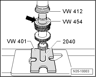
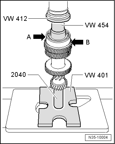
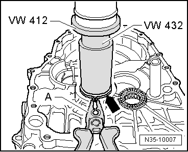
| t | Press tool -VW 412- |
| t | Thrust piece -VW 431- |
| t | Thrust piece -VW 432- |

| t | Thrust piece -VW 454- |
| t | Thrust piece -30–505- |
| t | Thrust plate -40-105- |
| t | Tube -2040- |
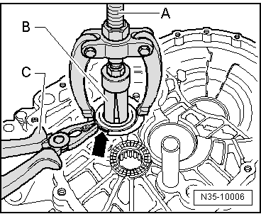
| t | Internal puller -1 - Kukko 21/5- |
| t | Splitter -3 - Kukko 17/1- |
| t | Splitter -3 - Kukko 17/2- |
| t | Puller -2 - Kukko 18/1- |
| t | Counter support -4- Kukko 22/2- |
 Note
Note| Install all bearings on input shaft with gear oil. |

| 1 - | Retaining ring |
| 2 - | Washer |
| q | Outer diameter = 78.6 mm |
| q | May be renewed only in modified gearbox housings. (From gearbox date 10 04 6) → Fig. |
| q | Allocation of components via → Electronic parts catalogue (ETKA) |
| 3 - | Gearbox housing |
| q | From gearbox date 10 04 6, modified in vicinity of seat for deep groove ball bearing → Item, washers → Item and → Item, → Fig. and → Fig. |
| q | Allocation of components via → Electronic parts catalogue (ETKA) |
| 4 - | Washer |
| q | Outer diameter = 85 mm |
| q | May be renewed only in modified gearbox housings. (From gearbox date 10 04 6) → Fig. |
| q | Allocation of components via → Electronic parts catalogue (ETKA) |
| 5 - | Retaining ring |
| q | If deep groove ball bearing → Item and input shaft → Item are renewed, redetermine → Fig. |
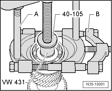
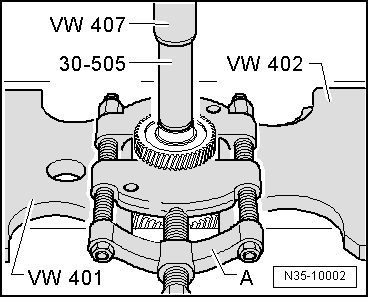
| 6 - | Deep groove ball bearing |
| q | Always renew |
| q | Pulling off → Fig. |
| q | Pressing on → Fig. |
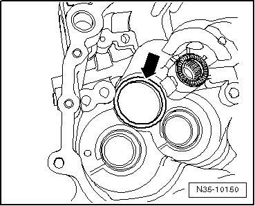
| 7 - | Gear wheel for 5th gear |
| q | Pressing off → Fig. |
| q | Installation position: peripheral groove -arrow- faces deep groove ball bearing → Item |
| q | Pressing on → Fig. |
| 8 - | Input shaft |
| q | With gear wheels for 3rd, 4th and 6th gears |
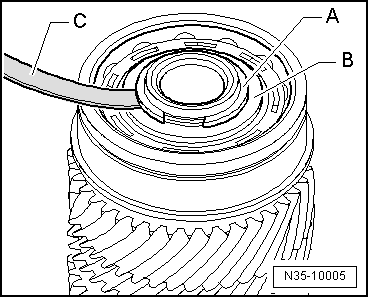
| 9 - | Cylindrical roller bearing |
| q | With retaining ring |
| q | Pulling out → Fig. |
| q | Pressing in → Fig. |
| q | Installation position: retaining ring in bearing faces input shaft |
| 10 - | Clutch housing |
|
|
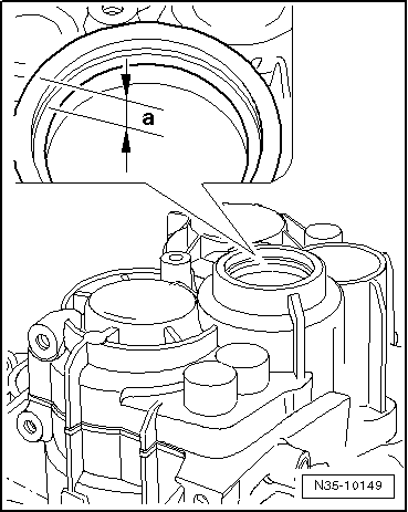
| Distance above deep groove ball bearing | Dimension „a“ |
| From gearbox date 10 04 6 | 10.7 mm |
| Through gearbox date 09 04 6 | 10 mm |
|
|
|
|
|
|
|
|
Note
|
|
| Measured value (mm) | Retaining ring thickness (mm) | Axial play (mm) |
| 0.01 … 0.05 | 1.86 | 0.01 … 0.05 |
| 0.05 … 0.07 | 1.89 | 0.01 … 0.05 |
| 0.07 … 0.10 | 1.92 | 0.01 … 0.05 |
| 0.10 … 0.13 | 1.95 | 0.01 … 0.05 |
| 0.13 … 0.16 | 1.98 | 0.01 … 0.05 |
|
|
|
|