
Golf Mk4
| Electrical and electronic components and their locations |
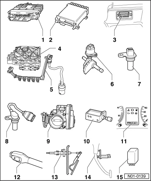
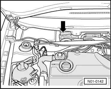
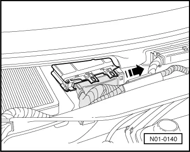
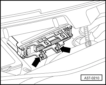
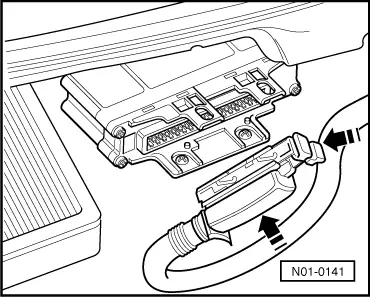
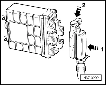
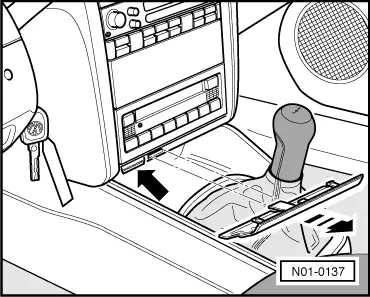
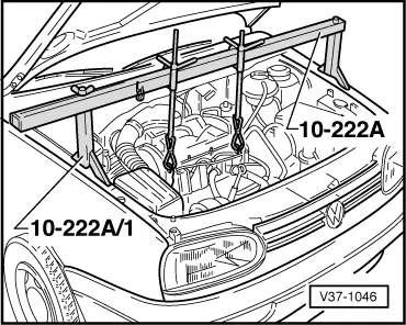
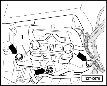
| 1 - | Control unit for automatic gearbox -J217- |
| Do not remove until electric and hydraulic faults have been eliminated as sources. |
| q | Location → Fig. |
| q | Removing → Fig.. |
| q | Installing → Fig. |
| q | Can be checked in “guided fault finding”. |
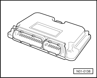
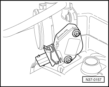
| 2 - | Engine control unit |
| q | Location and removing and installing → Fig.. |
| 3 - | Diagnostic connection |
| q | Location → Fig. |
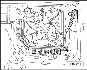
| 4 - | → Valve body |
| q | Location → Fig. |
| q | Removing and installing → Chapter |
| q | The → solenoid valves-N88-, -N89-, -N90-, -N91-, -N92-, -N93- and -N94- are attached to the → valve body. |
| q | Components can be checked in “guided fault finding”. |
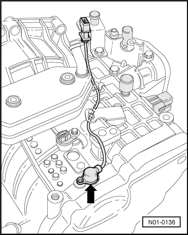
| 5 - | Conductor strip with integrated gearbox oil temperature sender -G93- |
| q | Location → Fig. |
| q | Removing and installing → Chapter |
| q | -G93- can be checked in “guided fault finding” |
| 6 - | Multifunction switch -F125- |
| q | Location and removing and installing → Fig.. |
| q | Can be checked in “guided fault finding”. |
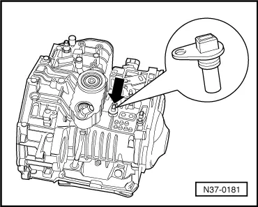
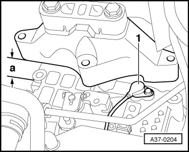
| 7 - | Gearbox speed sender -G38- |
| q | Location and removing and installing → Fig.. |
| q | 2-pin connector -T2- to wiring harness is white. |
| q | Can be checked in “guided fault finding”. |
| Do not interchange 2-pin connector -T2-, gearbox speed sender -G38- and driving speed sender -G68-! |
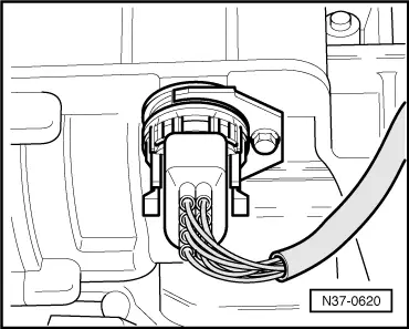
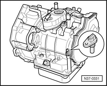
| 8 - | Vehicle speed sender -G68- |
| q | Location and removing and installing → Fig.. |
| q | 2-pin connector -T2- to wiring harness is black. |
| q | Can be checked in “guided fault finding”. |
| Do not interchange 2-pin connector -T2-, gearbox speed sender -G38- and driving speed sender -G68-! |
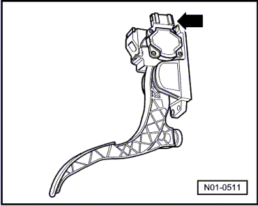
| 9 - | Throttle valve potentiometer -G69- or accelerator pedal position sender -G79- |
| q | More information → Anchor. |
| q | Can be checked in “guided fault finding”. |
| 10 - | Selector lever lock solenoid -N110- |
| q | Location: the selector lever lock solenoid is located on the selector lever |
| q | Removing and installing → Chapter |
| q | Can be checked in “guided fault finding”. |
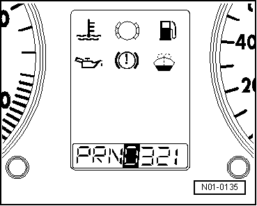
| 11 - | Selector lever position display -Y6- |
| q | Location → Fig. |
| q | Simultaneous illumination of all selector lever position display segments indicates gearbox emergency running mode. |
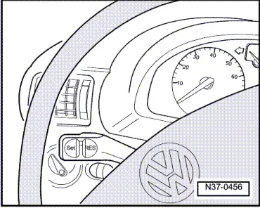
| 12 - | Cruise control system switch -E45- |
| q | Location → Fig. |
| q | Removing and installing → Electrical system; Rep. Gr.94. |
| q | Can be checked in “guided fault finding”. |
| 13 - | Kickdown switch -F8- |
| q | Location in vehicles without EPC → Fig.. |
| q | Location in vehicles with EPC → Fig.. |
| q | Can be checked in “guided fault finding”. |
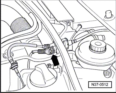
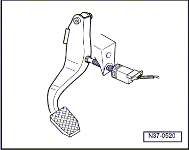
| 14 - | Brake light switch -F- or brake pedal switch -F47- |
| q | Location and removing and installing → Fig.. |
| q | Can be checked in “guided fault finding”. |
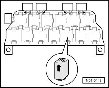
| 15 - | Starter inhibitor and reversing light relay -J226- |
| q | Location → Fig. |
|
|
|
|
|
|
|
|
|
|
|
|
|
|
|
|
|
|
|
|
|
|
|
|
|
|
|
|
|
|
|
|
|
|
|
|
|
|
|
|
|
|
|
|
|
|
|
|
|
|