volkswagen Workshop Repair Guides

Volkswagen Workshop Service and Repair Manuals

Transporting automatic gearbox > < Modifying support rails VW 457
Removing and installing gearbox
Required tools → Chapter
Installing → Anchor
Torque settings → Chapter
–  Disconnect battery earth strap → Vehicle electrics; Rep. Gr.27.
–  Remove battery.
–  Remove battery carrier.
–  Remove engine cover.
   
–  Also remove complete air filter.
–  Pull intake hose -1- and connector -2- off air mass meter.
–  Pull off vacuum hose -3-.
–  Then remove bolts -4- and -5-.
–  Remove complete air filter.
–  Disconnect speedometer connector at gearbox.
  A37-0192
–  Pull off electrical connections -1- through -4-.
1 - To solenoid valves
2 - To vehicle speed sender -G68-
3 - Multifunction switch -F125-
4 - Gearbox speed sender -G38-
There are two versions of the gearbox speed sender -G38-, with and without cable.
–  Remove wiring loom from retainer on gearbox and place to the side.
–  Also remove retainer for power steering pressure line together with retainer for wiring harness.
–  Move selector lever to “P” position.
  A37-0193
–  Remove securing clip -3- from support bracket.
–  Pull selector lever cable -1- from selector shaft lever -4-.
–  Lay selector lever cable to side.
  A37-0194
–  Remove earth cable -1- from engine/gearbox connecting bolt.
–  Disconnect electrical connections -3- and -4- on starter.
–  Separate connector -2- and pull out of retainer.
–  Remove wiring harness retainer from starter.
–  Remove upper starter motor bolt.
  A37-0195
–  Clamp off and remove → ATF cooler hoses.
–  Seal connections with clean plugs.
–  Remove all upper engine/gearbox connecting bolts.
  A37-0196
–  Fit support device -10 - 222 A- with legs -10 - 222 A /1- and support engine with gearbox in this position.
–  Remove front left wheel bolts.
–  Raise vehicle.
–  Remove left wheel.
  V37-1046
–  Remove “insulation”.
  N37-0673
–  Remove left noise insulation.
Only for vehicles with TDI engine
–  Remove pressure pipe between charge air cooler and turbocharger.
Continuation for all vehicles
–  Remove right noise insulation.
  N37-0674
–  Remove shield.
  A37-0199
–  Remove bracket -1- for power steering pressure pipe from lower starter bolt -arrow-.
–  Remove lower starter bolt.
–  Remove starter -2-.
Vehicles with 1.4 l engine
–  Pull Lambda probe connector -3- out of retainer -4-.
–  Remove retainer from gearbox.
Continuation for all vehicles
–  Remove shield for right inner constant velocity joint, if fitted, from engine.
–  Unbolt drive shafts from gearbox.
–  Raise right drive shaft and secure.
Cable ties are appropriate because they will not damage the drive shaft.
  N37-0678
–  Remove pendulum support.
–  Unclip cover for torque converter nuts.
  A37-0200
–  Remove nuts “Qty. 3” from torque converter -arrow-.
–  To do this, turn crankshaft 120° for each bolt.
Vehicles with 1.4 l engine
–  Here, loosen torque nuts through hole above right drive shaft.
Continuation for all vehicles
–  Turn steering to left lock.
  A37-0201
–  Mark installation position of suspension link bolts on swivel joint and remove bolts.
–  Remove suspension link -arrow-.
  N40-0259
–  Separate left coupling rod -1- from suspension link and turn coupling rod upwards.
–  Swing wheel bearing housing outwards.
–  Guide left drive shaft -2- out between subframe and gearbox.
–  Raise drive shaft and secure.
Cable ties are appropriate because they will not damage the drive shaft.
  N39-0597
–  Remove bolts from left assembly mounting -2-.
–  Carefully tilt engine and gearbox. To do this, lower left spindle about 60 mm.
  N37-0675
–  Unbolt left bracket -1- from gearbox.
–  Separate exhaust system behind front pipe.
  N37-0676
–  Bolt on support rail -VW 457- at the two threaded holes for → pendulum support.
–  Insert several washers between subframe and rail. Total thickness must be at least 6 mm.
-A- Bolts → M8x25
–  Position engine support -3300 A- and secure with bolt -B-.
Vehicles with 1.4 l engine
–  Position engine support -3300 A- between gearbox and exhaust system.
Continuation for all vehicles
–  Tilt engine and gearbox forwards.
  N37-0660
–  Set up gearbox support -3282-.
The symbols on the adjusting plate -3282/2- indicate the supports required.
  V37-1049
–  Move engine and gearbox jack -V.A.G 1383 A- under gearbox and support gearbox.
  N37-0079
–  Set pin of safety support against oil sump and secure to gearbox housing.
  N37-0059
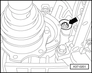
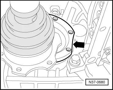
–  On vehicles with triple roller drive shafts, turn drive flange to right so that the flat is vertical.
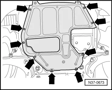
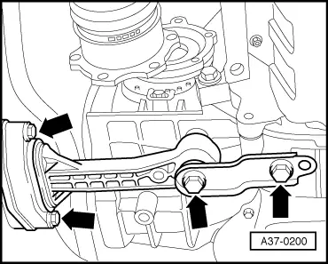
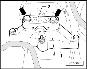
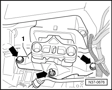
–  Remove lower engine/gearbox connecting bolts.
–  Press gearbox slightly off engine while simultaneously pressing torque converter out of drive plate.
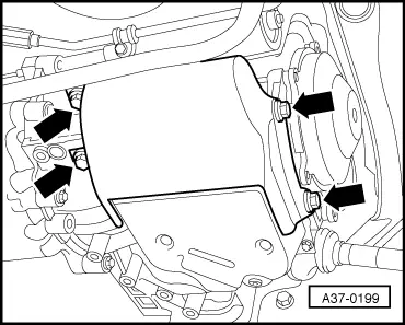
–  Press torque converter against → ATF pump.
–  Lower gearbox slightly.
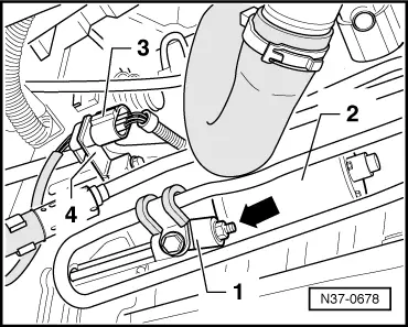
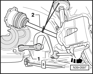
–  When doing this, guide power steering pressure line past gearbox.
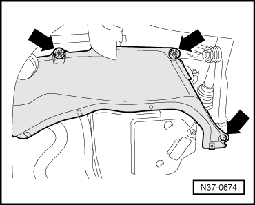
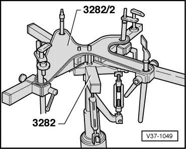
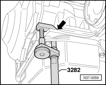
–  Tilt gearbox using spindle of gearbox support -3282- and, whilst lowering, guide cover on wheel housing side closely past wheel housing.
  N37-0680
–  Always ensure that right drive flange does not strike against engine, nor multifunction switch against subframe.
–  Secure torque converter to prevent it from falling out.
To raise gearbox, use a workshop hoist → Chapter.
Installing gearbox
–  Before installing gearbox in reverse order, note the following points:
t  The starter bush can be renewed as necessary → Chapter.
t  Check for proper seating of both dowel sleeves between engine and gearbox.
t  The torque converter must be properly installed; it must not have slid forwards. There are different versions of the torque converter which must not be mixed up. For further information about the torque converter → Chapter.
t  Check for proper seating of intermediate plate, if one is present.
  N01-0453
t  It must be possible to guide the engine and gear box together by hand until the flanges make contact all around.
t  If this is not so, then “something is wrong”!
t  Readjust the gearbox support until the engine and gearbox “are aligned with each other”.
t  Guide selector lever cable as soon as possible into its support bracket.
t  Align engine and gearbox mountings free of tension → Engines; Rep. Gr.10.
t  Torque settings → Chapter.
t  Always renew securing clip of selector lever cable on support bracket of gearbox. The selector lever cable must always be adjusted → Chapter.
t  After installing, check → ATF level → Chapter.
t  After installation, perform basic setting → Chapter.
  N01-0453

Transporting automatic gearbox > < Modifying support rails VW 457