
Golf Mk4
| Removing and installing differential |

| Special tools and workshop equipment required |
| t | Drive shaft fitting appliance -VW 391- |
| t | Oil seal extractor lever -VW 681- |
| t | Puller -3109- |
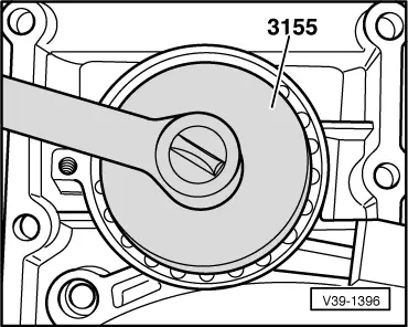
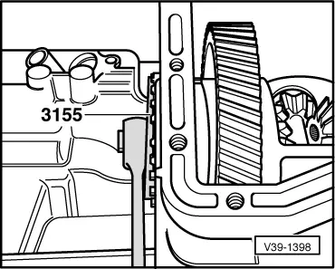
| t | Slotted nut wrench -3155- |
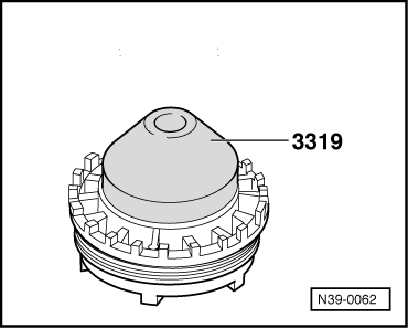
| t | Thrust piece -3319- |
|
| t | The pinion shaft does not need to be removed in order to remove and install the differential. |
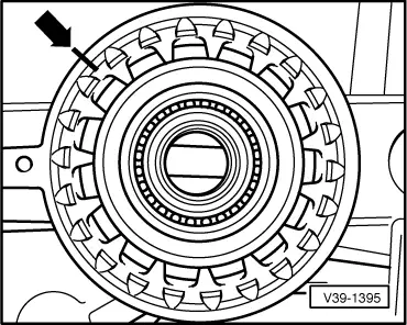
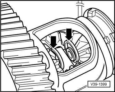
| t | If tapered roller bearings are to be reused, mark the adjusting ring → Fig.. |
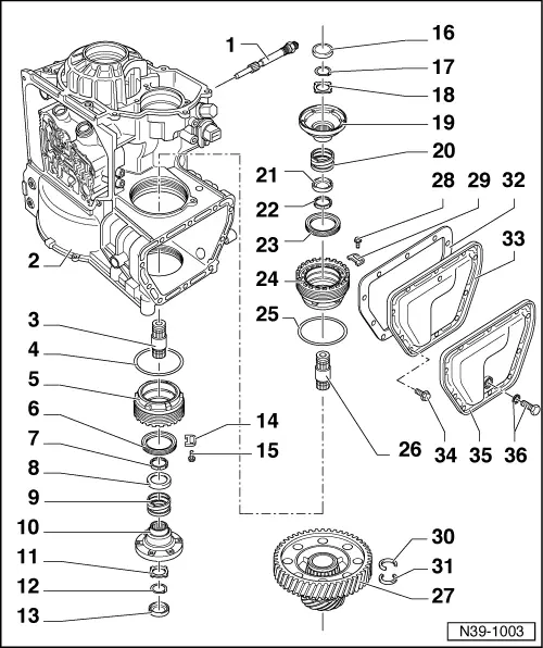
| 1 - | Speedometer drive |
| q | Oil level must be measured here if the gearbox cover does not have a plug → Chapter. |
| 2 - | Gearbox housing |
| 3 - | Output shaft |
| q | Inner thread faces flange during installation → Item |
| q | Shaft must be removed before differential can be removed |
| q | Install only after adjusting differential |
| 4 - | O-ring |
| q | Always renew |
| 5 - | Adjusting ring |
| If tapered roller bearings are to be reused, mark the adjusting ring → Fig.. When reinstalled, it must be set to this position again. |
| q | Removing and installing → Fig. |
| q | If new tapered roller bearings are used, the differential must be adjusted again → Chapter |
| 6 - | Drive flange oil seal |
| q | Can be renewed with gearbox installed → Chapter. |
| q | Remove with oil seal extractor lever -VW 681- |
| q | Before installing, half-fill space between sealing lips with sealing grease -G 052 128 A1-. |
| q | Driving in → Fig. |
| 7 - | Tapered ring |
| q | Shoulder faces thrust washer |
| 8 - | Thrust washer |
| q | Place over compression spring |
| 9 - | Compression spring |
| 10 - | Drive flange |
| q | Always remove flange before removing inner retaining ring from differential bevel gear. This will prevent the force of the compression spring from hindering the removal of the inner securing ring. |
| q | Insert with tapered ring, thrust washer and compression spring |
| q | Removing and installing with gearbox installed in order to renew oil seal → Chapter |
| 11 - | Dished spring |
| 12 - | Retaining ring |
| 13 - | Sealing cover |
| 14 - | Locking element |
| 15 - | Bolt, 12 Nm |
| 16 - | Sealing cover |
| 17 - | Retaining ring |
| 18 - | Dished spring |
| 19 - | Drive flange |
| q | Always remove flange before removing inner retaining ring from differential bevel gear. This will prevent the force of the compression spring from hindering the removal of the inner securing ring. |
| q | Insert with tapered ring, thrust washer and compression spring |
| q | Removing and installing with gearbox installed in order to renew oil seal → Chapter |
| 20 - | Compression spring |
| 21 - | Thrust washer |
| q | Place over compression spring. |
| 22 - | Tapered ring |
| q | Shoulder faces thrust washer |
| 23 - | Drive flange oil seal |
| q | Can be renewed with gearbox installed → Chapter. |
| q | Remove with oil seal extractor lever -VW 681- |
| q | Before installing, half-fill space between sealing lips with sealing grease -G 052 128 A1-. |
| q | Driving in → Fig. |
| 24 - | Bearing body, 150 Nm |
| q | Remove using slotted nut wrench -3155- |
| q | Installing → Fig. |
| 25 - | O-ring |
| q | Always renew |
| 26 - | Output shaft |
| q | Inner thread faces drive flange during installation → Item |
| q | Shaft must be removed before differential can be removed |
| q | Install only after adjusting differential |
| 27 - | Differential |
| q | Dismantling and assembling → Chapter |
| q | After adjusting differential, always secure bearing body → Item and adjusting ring → Item |
| 28 - | Bolt, 12 Nm |
| 29 - | Locking element |
| 30 - | Inner retaining ring |
| q | Keep in mind that during installation and removal, the compression spring should not be applying force. |
| q | Removing and installing → Fig. |
| 31 - | Inner retaining ring |
| q | Keep in mind that during installation and removal, the compression spring should not be applying force. |
| q | Removing and installing → Fig. |
| 32 - | Seal |
| q | Always renew |
| 33 - | Cover for final drive |
| q | “Older” version without inspection plug |
| q | As replacement part, only with inspection plug → Item |
| 34 - | Bolt, 28 Nm |
| q | Insert with locking fluid -AMV 185 101- |
| 35 - | Cover for final drive |
| q | “New” version with inspection plug |
| 36 - | Inspection plug |
| q | Checking gear oil with gearbox installed → Chapter. |
|
|
|
|
|
|
|
|
|
|
|
|