volkswagen Workshop Repair Guides

Volkswagen Workshop Service and Repair Manuals

Test table > < Gearbox: Electrical check
Automatic gearbox 01M self-diagnosis
Gearbox: Electrical check
Electrical check
 
N01-0142
  • ‒ Switch off ignition, open bonnet.
  • ‒ → Release multi-pin connector, then pull connector off control unit.
 
N37-0139
  • ‒ → Fit test box V.A.G 1598/18 onto multi-pin connector (1) and lock, in direction of arrow (2).

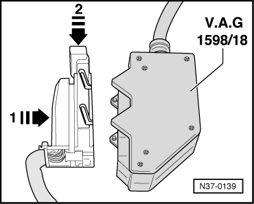
Using test box V.A.G 1598/18 the wiring can be checked according to current flow diagram.

  • ‒ Before connecting the test leads the correct measuring range on tester must be adjusted. Otherwise the electronic components can be destroyed !
  • ◆ Use the hand multimeter V.A.G 1526 with auxiliary cables from V.A.G 1594 for testing.
  • ◆ The specified values are valid for an ambient temperature from 0 °C...40 °C.
  • ◆ If the readings obtained differ from the specified values, determine fault on the basis of the current flow diagram.
  • ◆ If the readings obtained differ only slightly from the specified values, clean sockets and connectors of the testers and test leads and repeat test. Before replacing the particular components, test wiring and connections and, particularly if specified values are below 10 ω, repeat resistance measurement on component.
 
N01-0141

After electrical checks

  • ‒ → Locate multi-pin connector on control unit -J217- pins (arrows) then lock multi-pin connector.
  • ‒ Performing self-diagnosis .
  • ‒ Initiating basic setting => Page 01-54 .

Control unit -J217- multi-pin connector (68 pin) assignment (sockets on V.A.G 1598/18)

1-

Earth (terminal 31)

20-

Road speed sender -G68-

2-

Vacant

21-

Gearbox speed sender -G38-

3-

Data bus Low input and output signals

22-

Solenoid valve 6 -N93- supply voltage

4-

Vacant

23-

Supply voltage (terminal 15)

5-

Throttle valve potentiometer signal -G69-1)

24-

Diagnosis K-wire

6-

Gearbox oil temperature (ATF) sender -G93-

25-

Data bus High input and output signals

7-

Vacant

26-

Data bus screening, vacant if the core of the Data bus wiring is interwoven

8-

Only vehicles with Tiptronic: Shift up

27-

Vacant

9-

Solenoid valve 3 -N90-

28-

Throttle valve potentiometer -G69- earth1)

10-

Solenoid valve 7 -N94-

29-

Selector lever lock solenoid -N110-

11-

Park/neutral signal

30-

Vacant

12-

Kickdown for air conditioner 1)

31-

Demand: Radiator fan

13-

Ignition timing influence 1)

32-

Vacant

14-

Vacant

33-

Vacant

15-

Brake light switch -F- signal voltage

34-

Vacant

16-

Kickdown switch -F8-

35-

Vacant

17-

Vacant

36-

Vacant

18-

Multi-function switch -F125- (pin 5)

37-

Vacant

19-

TD (revolution) signal 1)

38-

Vacant

1)     Only used on vehicles without Data bus. On vehicles with Data bus these chambers are not used. The control unit then receives this information from the Data bus, or sends the information or the Data bus (3 + 25).

39-

Tiptronic gate switch, or vacant

54-

Solenoid valve 2 -N89-

40-

Multi-function switch -F125- (pin 2)

55-

Solenoid valve 1 -N88-

41-

Load signal from engine control unit 1)

56-

Solenoid valve 5 -N92-

42-

Vacant

57-

Selector lever display

43-

Road speed sender -G68- (screening)

58-

Solenoid valve 6 -N93-

44-

Gearbox speed sender -G38- (screening)

59-

Vacant, or brake pressure switch

45-

Supply voltage (terminal 30)

60-

Vacant

46-

Vacant

61-

Cruise control system (output) 1)

47-

Solenoid valve 4 -N91-

62-

Multi-function switch -F125- (pin 6)

48-

Freewheel lock (only on Syncro vehicles)

63-

Multi-function switch -F125- (pin 1)

49-

Vacant

64-

Vacant

50-

Throttle valve potentiometer -G69- (5 volt)1)

65-

Road speed sender -G68-

51-

Vacant or diagnostic lamp OBDII fault

66-

Gearbox speed sender -G38-

52-

Only vehicles with Tiptronic: shift down

67-

Solenoid valves voltage supply

53-

Vacant

68-

Vacant

1)     Only used on vehicles without Data bus. On vehicles with Data bus these chambers are not used. The control unit then receives this information from the Data bus, or sends the information or the Data bus (3 + 25).

List of test steps

    Only perform test steps for the relevant component as listed in fault finding table and measured value block.

Component checked

Component checked

Supply voltage from control unit -J217-

- Perform test step 1

Kick-down switch -F8-

- Perform test step 10

Brake light switch -F-

- Perform test step 2

Selector lever lock solenoid -N110-

- Perform test step 11

Solenoid valve 1 -N88-

- Perform test step 3

Gearbox oil temperature sender -G93- (ATF)

- Perform test step 12

Solenoid valve 2 -N89-

- Perform test step 4

Road speed sender -G68-

- Perform test step 13

Solenoid valve 3 -N90

- Perform test step 5

Gearbox oil temperature sender -G93- (ATF)

- Perform test step 14

Solenoid valve 4 -N91-

- Perform test step 6

Multi-function switch
-F125-

- Perform test step 15

Solenoid valve 5 -N92-

- Perform test step 7

Solenoid valve 6 -N93-

- Perform test step 8

Solenoid valve 7 -N94-

- Perform test step 9

Test table > < Gearbox: Electrical check