
Golf Mk4
|
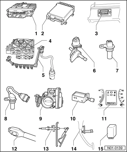
Locations of electrical/electronic components
Locations of electrical/electronic components
|
 |
|
If engine or gearbox control units are replaced, the system must be brought to basic setting => page 01-54 , Initiating basic setting.
|
|
|
|
|
|
|
|
|
|
 |
|
|
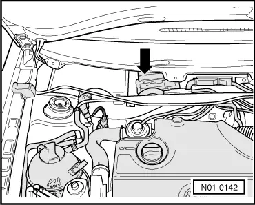
→ Fig.1 Engine control unit Location: The control unit is located in plenum chamber. Removing and installing control unit |
 |
|
|
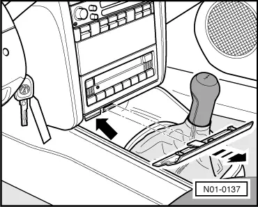
→ Fig.2 Diagnosis connections Location: The diagnosis connection -arrow- is located behind the cover above the ashtray. |
 |
|
|
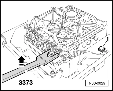
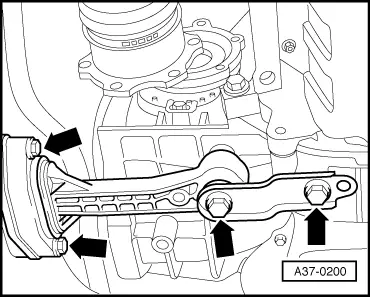
→ Fig.3 Valve body Location: The valve body is located above oil pan. The solenoid valves -N88-, -N89-, -N90-, -N91-, -N92-, -N93- and -N94- are attached to the valve body. Removing and installing valve body => Repair group 38; Removing and installing valve chest in booklet:
|
|
|
|
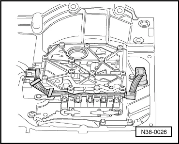
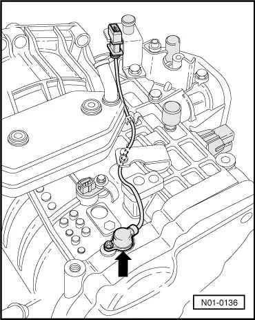
→ Fig. 4 Conductor strip with integrated gearbox oil temperature sender (ATF) -G93- Location: The conductor strip is located in the oil pan on the valve chest. |
 |
|
|
→ Fig.5 Removing and installing conductor strip The conductor strip can be changed with gearbox installed without removing the valve body. Do not kink or damage the conductor strip. Removing and installing conductor strip
If the locating points are damaged the valve body must be exchanged. Installation is performed in the reverse order. Do not kink or damage the conductor strip. Removing and installing valve body => Repair group 38; Removing and installing valve chest in booklet:
|

 |
|
|
Installation is performed in the reverse order.
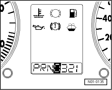
→ Fig.7 Selector lever position display -Y5- Location: Selector lever position display (arrow) is located in combi-instrument. Removing and installing selector lever position display. => Repair group 90; Removing and installing dash panel insert |
 |
|
|
→ Fig.8 Throttle valve potentiometer -G69- Locations: On a petrol engine the potentiometer is a component part of the throttle valve control part -J338-. It can be found on the throttle valve housing (engine). On a Diesel engine the "Throttle valve signal" is generated in the sender for accelerator pedal position -G79-. The sender can be found near the accelerator pedal. For self-diagnosis: The throttle valve potentiometer is one of the engine control unit sensors. However the gearbox control unit also requires the throttle valve potentiometer signal. For this reason the signal from the engine control unit is transmitted to the automatic gearbox control unit. On vehicles with Data bus the automatic gearbox control unit receives the throttle valve potentiometer signal from the Data bus. On vehicles without Data bus the signal is made available via a wire from the engine control unit. The self-diagnosis of the automatic gearbox only checks the signal, not the potentiometer! On vehicles without Data bus the wire for the signal is also checked. The signal can only be read-out in measured value block. => Read measured value block ; Display group number 001 and 003 It is therefore imperative that the self-diagnosis of the engine control unit is also carried out when the self-diagnosis indicates that the throttle valve potentiometer is faulty. Checking and adjusting or removing and installing throttle valve potentiometer Petrol engine => Repair group 24; depending on engine code Diesel engine |
 |
|
|
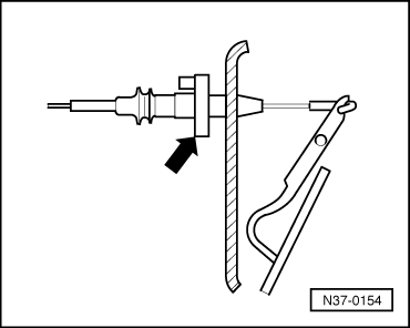
→ Fig.9 Kickdown switch -F8- Locations: The kickdown switch (arrow) is integrated into accelerator cable and is located on bulkhead in engine compartment. On vehicles which do not have an accelerator cable the kick-down signal is generated in the sender for accelerator pedal position -G79-. The sender can be found close to the accelerator pedal. For self-diagnosis: On these vehicles the kick-down switch signal is transmitted from the engine control unit to the automatic gearbox control unit. On vehicles with Data bus the automatic gearbox control unit receives the kick-down signal from the Data bus. On vehicles without Data bus the signal is received via a wire from the engine control unit. Removing and installing kickdown switch Petrol engine
=> Repair group 20; Adjusting accelerator cable Diesel engine |
 |
|
|
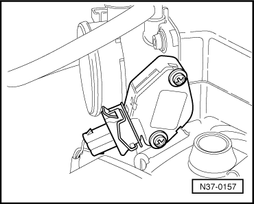
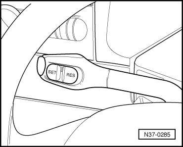
→ Fig.10 Cruise control system switch -E45- Location: Cruise control switch is located on steering column switch. Removing and installing cruise control switch |
 |
|
|
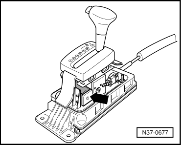
→ Fig.11 Selector lever lock solenoid -N110- Location: The selector lever lock solenoid -arrow- is located in the selector lever housing. Removing and installing selector lever lock solenoid => Repair group 37; Servicing selector lever mechanism in booklet:
|
 |
|
|
→ Fig.12 Brake light switch -F- Location: Brake light switch (arrow) is located on pedal cluster. Removing and installing brake light switch => Repair group 47; Assembly overview: Pedal cluster, brake pedal |
 |
|
|
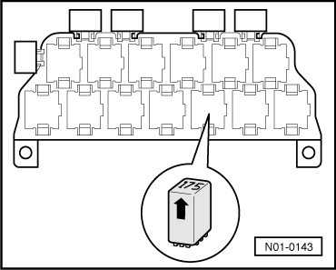
→ Fig.13 Relay for starter inhibitor and reversing light -J226- Location: Relay located on additional relay carrier under dash panel, left. Relay is marked with number "150" (arrow). |
 |
|
|
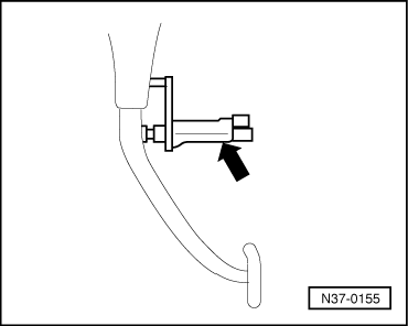
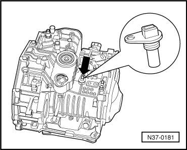
→ Fig.15 Road speed sender -G68- Location: The road speed sender -arrow- is located on top of gearbox. When the gearbox is installed the sender is covered by the left assembly mounting. Removing and installing road speed sender Additional information
Special tools, testers and auxiliary items
=> Repair group 37; Removing and installing gearbox
|
 |
|
|
 |
|
|
 |
|
|
 |
|
Installation is performed in the reverse order.
Tightening torques => Repair group 37; Removing and installing gearbox in booklet:
|
 |
|
|
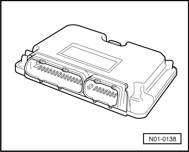
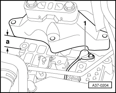
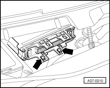
Location of control unit for automatic gearbox -J217- → The control unit -arrow- is located in plenum chamber centre/right. |
 |
|
|
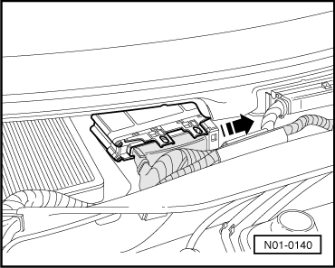
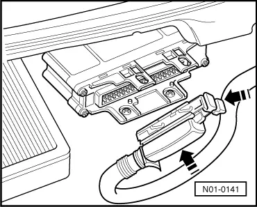
Removing control unit
|
 |
|
|
 |
|
|
Installing control unit Installation is performed in the reverse order. |