
Golf Mk4
| Dismantling and assembling pistons and conrods |
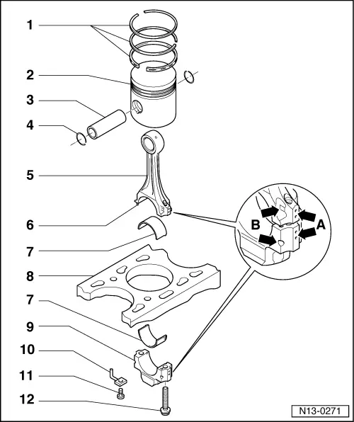
| 1 - | Piston rings |
| q | Offset gaps by 120°. |
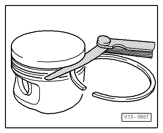
| q | Remove and install using piston ring pliers. |
| q | “TOP” faces towards piston crown. |
| q | Checking ring gap → Fig.. |
| q | Checking ring-to-groove clearance → Fig.. |
| 2 - | Piston |
| q | With combustion chamber. |
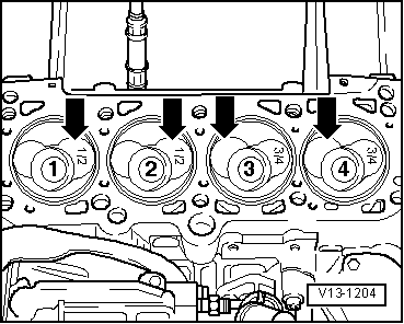
| q | Mark installation position and cylinder number. |
| q | Installation position and allocation of piston to cylinder → Fig. |
| q | Arrow on piston crown points to pulley end. |
| q | Install using piston ring clamp. |
| q | If piston skirt is cracked, renew piston. |
| q | Checking piston projection at TDC → Chapter. |
| 3 - | Piston pin |
| q | If difficult to remove, heat piston to 60 °C. |
| q | Remove and install with drift -VW 222 A-. |
| 4 - | Circlip |
| 5 - | Conrod |
| q | Renew as set only. |
| q | Mark cylinder number -A- |
| q | Installation position: marking -B- faces towards pulley end |
| 6 - | Fitted pin |
| q | The dowel pins must sit firmly in the conrod, not in the cover |
| 7 - | Bearing shell |
| q | Observe different types: on engine code AHF, ASV, upper bearing shell (towards piston) is made of a more wear resistant material and can be identified by a black line on the bearing surface in the area of the joint. |
| q | Note installation position. |
| q | Do not interchange used bearing shells. |
| q | Ensure retaining lug fits tightly in recess |
| q | Axial clearance wear limit: 0.37 mm. |
| q | Measure radial clearance with Plastigage: Wear limit: 0.08 mm, do not rotate crankshaft when measuring radial clearance. |
| 8 - | Cylinder block |
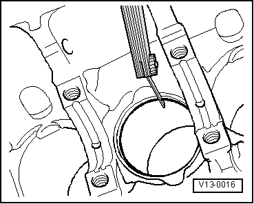
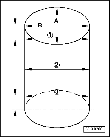
| q | Checking cylinder bores → Fig.. |
| q | Piston and cylinder dimensions → Chapter. |
| 9 - | Conrod bearing cap |
| q | Note installation position. |
| 10 - | Oil spray jet |
| q | For piston cooling. |
| 11 - | 25 Nm |
| q | Insert without sealant. |
| 12 - | Conrod bolt, 30 Nm + 1/4 turn (90°) further |
| q | Renew. |
| q | Oil threads and contact surface. |
| q | Use old bolts to measure radial clearance. |
|
|
| Piston ring dimensions in mm | New | Wear limit |
| 1st compression ring | 0.20 …0.40 | 1.0 |
| 2nd compression ring | 0.20 …0.40 | 1.0 |
| Oil scraper ring | 0.25 …0.50 | 1.0 |
|
|
| Piston ring dimensions in mm | New | Wear limit |
| 1st compression ring | 0.06 …0.09 | 0.25 |
| 2nd compression ring | 0.05 …0.08 | 0.25 |
| Oil scraper ring | 0.03 …0.06 | 0.15 |
 Note
Note
|
|