
Golf Mk4
|
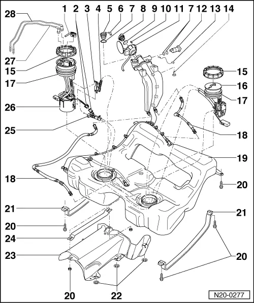
| 1 - | Connector |
| q | Black, 4-pin. |
| 2 - | Connector |
| q | Black, 2-pin. |
| 3 - | Return hose bracket |
| 4 - | Return hose |
| 5 - | Gravity/overflow valve |
| q | To remove valve unclip upwards out of support. |
| q | Check valve for through-flow; valve vertical: open, valve tilted 45°: closed |
| 6 - | Angled piece |
| 7 - | O-ring |
| q | Renew |
| 8 - | Cap |
| 9 - | Seal |
| q | Renew if damaged. |
| 10 - | Securing bolt |
| 11 - | Tank flap unit |
| q | With rubber cup. |
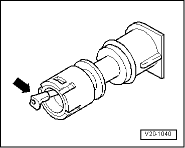
| 12 - | Breather valve |
| q | To remove valve unclip sideways out of support. |
| q | Unscrew cap before installing |
| q | Checking → Fig.. |
| 13 - | Earth connection |
| q | Check for secure seating. |
| 14 - | 10 Nm |
| 15 - | Union nut |
| q | Remove and install using union nut tool -3217-. |
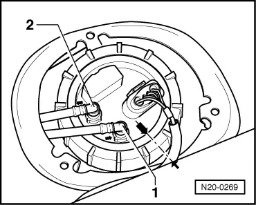
| 16 - | Fuel gauge sender 2 -G169- |
| q | Note installation position on fuel tank → Fig. |
| q | To remove, pull supply hose off fuel pump, unclip return hose retainer from fuel pump and separate 2-pin connector → Chapter Removing and installing fuel pump |
| q | Only renew complete with supply and return hoses. |
| q | Checking: → Current flow diagrams, Electrical fault finding and Fitting locations Guided fault finding with VAS 5051 |
| 17 - | Seal |
| q | Renew if damaged. |
| q | When installing, insert seal dry into fuel tank opening. |
| q | Moisten with fuel only when installing flange. |
| 18 - | Breather line |
| q | Clipped onto top of fuel tank. |
| q | Check for secure seating. |
| 19 - | Fuel tank |
| q | When removing, support with engine and gearbox jack -V.A.G 1383 A- |
| q | Removing and installing → Chapter. |
| 20 - | 25 Nm |
| 21 - | Securing strap |
| q | Note differing lengths. |
| 22 - | Clamping washer |
| 23 - | Heat shield |
| 24 - | Retaining strut |
| 25 - | Supply hose |
| q | To remove from fuel pump press release button on connecting piece |
| 26 - | Fuel pump for advanced delivery -G6- |
| q | With fuel gauge sender -G- |
| q | Note installation position on fuel tank → Fig.. |
| q | Removing and installing → Chapter. |
| q | Checking fuel pump → Chapter |
| q | Clean strainer if soiled. |
| 27 - | Return line |
| q | From fuel filter → Chapter. |
| q | Blue or with blue marking. |
| q | Clipped onto fuel tank |
| q | Check for secure seating. |
| q | To pull off flange, press release button on connecting piece |
| 28 - | Supply line |
| q | To fuel filter → Chapter. |
| q | Clipped onto fuel tank |
| q | Check for secure seating. |
| q | Black |
| q | To pull off flange, press release button on connecting piece |
 Note
Note
|
|