volkswagen Workshop Repair Guides

Volkswagen Workshop Service and Repair Manuals

Aligning engine and gearbox mountings > < Securing engine to assembly stand
Notes on installing
Notes on installing
Installation is carried out in the reverse order. When installing, note the following:
  Caution
When doing any repair work, especially in the engine compartment, pay attention to the following due to the cramped conditions:
t  Route all the various lines (e.g. for fuel, hydraulics, activated charcoal filter system, coolant and refrigerant, brake fluid and vacuum) and electrical wiring in their original positions.
t  To avoid damage to lines, ensure sufficient clearance to all moving or hot components.
–  Check clutch release bearing for wear and renew if necessary.
–  Lightly grease clutch release bearing, release bearing guide sleeve and splines on input shaft with G 000 100.
–  Check whether dowel sleeves for centring engine/gearbox have been fitted in cylinder block, insert if necessary.
   
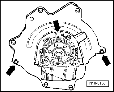
–  Hook intermediate plate onto sealing flange and slide onto dowel sleeves -arrows-.
–  Ensure that the intermediate plate is correctly located on engine.
–  When swinging engine in, ensure that there is clearance between drive shafts.
Vehicles with manual gearbox
–  If necessary, make sure that clutch plate is properly centred.
–  Check clutch release bearing for wear and renew if necessary.
–  Lightly grease clutch release bearing, release bearing guide sleeve and splines on input shaft with G 000 100.
–  Install hydraulic clutch slave cylinder → 5-speed manual gearbox 02K; Rep. gr.30.
–  Install selector mechanism → 5-speed manual gearbox 02K; Rep. gr.34.
Vehicles with automatic gearbox
–  Only use nuts approved in parts programme to secure torque converter to drive plate.
–  Install selector lever cable to gearbox. Adjust if necessary. → Automatic gearbox 01M; Rep. gr.37.
Continuation for all vehicles
–  Align engine and gearbox mountings → Chapter.
–  Install drive shafts → Running gear, axles, steering, front and four-wheel drive; Rep. gr.40.
–  Install front exhaust pipe → Chapter.
–  Install power steering vane pump: → Running gear, axles, steering - Front and four-wheel drive; Rep. gr.48
–  Install air conditioner compressor.
–  Electrical connections and routing: → Electrical system; Rep. gr.97.
–  Install poly V-belt → Chapter.
–  Adjusting throttle cable → Chapter.
–  Install centre, left and right noise insulation: → General body repairs, exterior; Rep. gr.50
–  Replenish coolant → Chapter.
–  Install air filter → Fig..
Engine codes APE, ATN, AUS, AXP, AZD, BCA, BCB
  Note
If a new engine control unit is installed, the throttle valve module -J338- needs to be cleaned prior to adaptation → Chapter.
Continuation for all vehicles
–  Connect Vehicle diagnosis, testing and information system -VAS 5051-.
–  Clear learnt values and adapt engine control unit to throttle valve module and exhaust gas recirculation valve -N18- → Vehicle diagnostic tester„Guided functions“.
–  Carry out vehicle system test → Vehicle diagnostic tester„Guided fault finding“.
–  Finish the vehicle system test so that any fault entries stored during assembly can be deleted automatically.
Observe applicable safety precautions during road test.
–  Carry out a road test.
–  Then carry out vehicle system test again and rectify any faults which may have occurred.
  N10-0160

Aligning engine and gearbox mountings > < Securing engine to assembly stand