volkswagen Workshop Repair Guides

Volkswagen Workshop Service and Repair Manuals

Securing engine to assembly stand > < Removing and installing engine
Notes on removing
Notes on removing
–  First check whether a coded radio is fitted. If so, obtain anti-theft coding.
–  The engine is removed upwards together with the gearbox.
–  With ignition switched off, disconnect earth strap from battery.
–  Bring lock carrier into service position → General body repairs, exterior; Rep. gr.50.
–  All cable ties which are opened or cut through when engine is removed must be replaced in the same position when engine is installed.
  WARNING
Steam may escape when expansion tank is opened. Wear eye protection and protective clothing to avoid eye injuries and scalding. Cover cap with cloth and open carefully.
–  Open and close expansion tank cap to release pressure in cooling system.
   
–  Remove battery and battery carrier.
–  Unclip cable guide from battery to plenum bulkhead.
–  Place positive wire from battery to starter motor to one side (remove together with assembly).
–  Unclip accelerator cable from upper part of air filter.
–  Unhook accelerator cable from cable support bracket and throttle valve module (do not remove locating clip).
–  Remove air filter → Fig..
  WARNING
Fuel supply lines are under pressure! Wear eye protection and gloves to avoid injuries and skin contact. Before loosening hose connections, wrap a cloth around the connection. Then release pressure by carefully pulling hose off connection.
  A10-0116
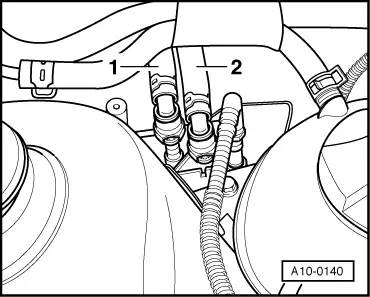
–  Now separate fuel supply and fuel return lines -1- and -2- (press release button).
–  Loosen or separate the following components:
t  Hose to activated charcoal filter system from intake manifold
t  Vacuum hose to brake servo from intake manifold
t  Connector from engine speed sender below oil dipstick tube bracket, and pull connector out of retainer
t  Connectors from ignition transformer, Hall sender and throttle valve module
t  Connectors from coolant temperature sender, oil pressure switch and exhaust gas recirculation valve -N18-
t  Connectors from injectors
Vehicles with manual gearbox
–  Remove selector mechanism from gearbox → 5-speed manual gearbox 02K; Rep. gr.34.
Vehicles with automatic gearbox
–  Remove selector lever cable from gearbox → Automatic gearbox 01M; Rep. gr.37.
Continuation for all vehicles
–  Remove noise insulation: → General body repairs, exterior; Rep. gr.50.
–  Loosen or separate the following components:
t  Connector of Lambda probe
t  The 2-pin connector from knock sensor (rear of cylinder block) and the 4-pin connector from intake manifold pressure sender, front right under intake manifold
–  Drain coolant → Chapter.
–  Loosen hose clips and pull coolant hoses off coolant thermostat housing.
–  Loosen bolts securing pulley from power steering vane pump.
–  Remove poly V-belt → Chapter.
–  Unbolt power-assisted steering vane pump and secure to subframe with wire, hoses remain connected → Running gear, axles, steering front and four-wheel drive; Rep. gr.48.
Vehicles with air conditioner
–  Remove air conditioner compressor.
–  Observe additional information and installation work → Chapter.
Vehicles with manual gearbox
–  Remove hydraulic clutch slave cylinder → 5-speed manual gearbox 02K; Rep. gr.30.
  Note
Clutch pedal must not be depressed.
Continuation for all vehicles
–  Pull radiator coolant hoses off engine using spring-type clip pliers -VAS 5024A-.
  A10-0140
–  Disconnect pendulum support -arrows-.
–  Pull vacuum and breather hoses off engine.
–  Disconnect all electrical wiring from gearbox, alternator and starter and lay to side.
–  Disconnect front exhaust pipe from exhaust manifold → Chapter.
–  Remove securing clamps for power-assisted steering pressure line.
–  Pull off or disconnect all other electrical connections as necessary from engine and lay to side.
–  Unbolt left and right drive shafts from gearbox and tie up: → Running gear, axles, steering; Front and four-wheel drive; Rep. gr.40
  A37-0200
–  Attach lifting tackle -2024 A- as follows and lift slightly with workshop crane -VAS 6100-:
Belt pulley end: 3rd hole in hook rail at position 1
Flywheel end: 3rd hole in hook rail at position 5
  Caution
Use securing pins on hooks and locking pins to avoid damage to engine and vehicle.
  Note
t  The positions marked 1…4 on the bar must be towards the belt pulley end.
t  The holes in the hook rails are counted up from the hook.
–  Remove cooling system expansion tank and lay to side.
–  Remove power-assisted steering reservoir and tie it up.
–  Remove activated charcoal filter.
  N10-0096
–  Remove engine mounting -A- and gearbox mounting -B-. To do this, unscrew bolts -1-, -2- and -3-.
Slightly turn assembly towards left side (engine towards front, gearbox towards back) and carefully lift out engine upwards.
  Note
When lifted out, the assembly must be carefully guided to prevent damage to the bodywork.
  N10-0161

Securing engine to assembly stand > < Removing and installing engine