volkswagen Workshop Repair Guides

Volkswagen Workshop Service and Repair Manuals

Installing > < Removing and installing cylinder head
Removing
Removing
–  First check whether a coded radio is fitted. If so, obtain anti-theft coding.
–  With the ignition switched off, disconnect battery earth strap.
   
–  Remove cover above camshaft housing -arrows-.
–  Open and close expansion tank cap to release pressure in cooling system.
–  Drain coolant → Chapter.
–  Loosen hose clips and pull coolant hoses off coolant thermostat housing.
  N24-0739
–  Remove plug -1-.
–  Unclip accelerator cable from upper part of air filter (only for engine codes AHW and AKQ).
–  Pull crankcase breather hose -2- off upper part of air filter.
–  Disconnect hose for hot air intake from hot air collector plate.
–  Loosen air filter and intake hose by means of securing bolts indicated by -arrows-.
–  Remove air filter.
  Note
t  Self-tapping screws are used as standard to secure air filter to plastic intake pipe and upper part of air filter to lower part of air filter. When these screws are loosened or tightened using a power tool, the threads in the intake manifold or the lower part of air filter may be damaged.
t  Therefore, the use of a power tool can only be allowed when:
t  the maximum speed of the power tool is 200 rpm,
t  a specified torque of max 3 Nm is set.
–  Remove oil dipstick guide tube.
–  Unhook accelerator cable from cable support bracket and throttle valve module (do not remove locating clip).
  WARNING
Fuel supply lines are under pressure! Wear eye protection and gloves to avoid injuries and skin contact. Before loosening hose connections, wrap a cloth around the connection. Then release pressure by carefully pulling hose off connection.
  N15-0312
–  Now separate fuel supply and fuel return lines (press release button).
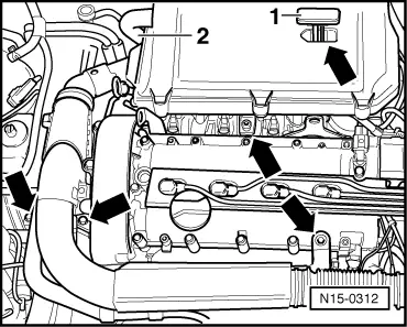
–  Loosen or separate the following components:
t  Hose from crankcase breather
t  Hose to activated charcoal filter system from intake manifold
t  Vacuum hose to brake servo from intake manifold
t  Vacuum hose between exhaust gas recirculation valve -N18- and junction of vacuum hose to brake servo
t  The 2-pin connector from knock sensor 1 -G61- (rear of cylinder block) and the 4-pin connector from intake manifold pressure sender -G71-, front right under intake manifold
t  The connector from engine speed sender -G28- beneath dipstick pipe bracket and pull connector out from bracket
t  Connectors from ignition transformer -N152-, Hall sender -G40- and throttle valve module -J338-
t  Connector from coolant temperature sender -G62-, oil pressure switch -F1- and exhaust gas recirculation valve -N18-
t  Connectors from injectors
–  Remove camshaft housing → Chapter.
–  Detach front exhaust pipe from exhaust manifold .
Engine codes APE, ATN, AUS, AXP, AZD, BCA, BCB only
  Note
In the case of vehicles with air-conditioner, the bracket for ancillaries must be removed before the exhaust manifold can be removed.
Removing and installing bracket on vehicles with air conditioner: → Heating, air conditioning; Rep. gr.87
Continuation for all vehicles
–  Remove exhaust manifold.
  A10-0140
–  Now the engine must be lifted slightly with spindle -B-.
  Note
Both lifting eyes are located on the cylinder head, so an additional bracket must be secured to the cylinder block to support the engine.
–  Screw retainer -T10014-, as illustrated, into cylinder block threaded hole in vicinity of coolant pump. Specified torque: 20 Nm.
–  Lift engine slightly using second spindle -A- until spindle -B- is relieved.
–  Remove spindle -B-.
–  Pull clamp securing coolant pipe to coolant pump off thermostat housing.
  N15-10360
–  Loosen cylinder head bolts in sequence given and then remove completely.
–  Carefully remove cylinder head.
  N15-0026

Installing > < Removing and installing cylinder head