| –
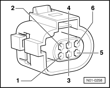
| Check wiring between test box and 6-pin connector for open circuit referring to current flow diagram. Contact 2 and test box socket 96, contact 4 and test box socket 84, contact 6 and test box socket 108, wire resistance:: max. 1.5 Ω. |
| –
| Additionally check wiring for short circuit to one another and short circuit to positive or earth. |
| If the specification is obtained: |
| –
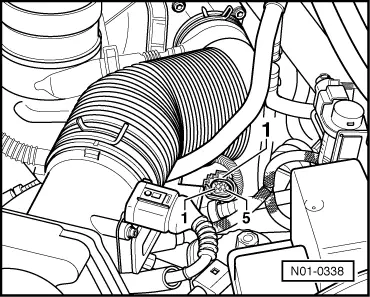
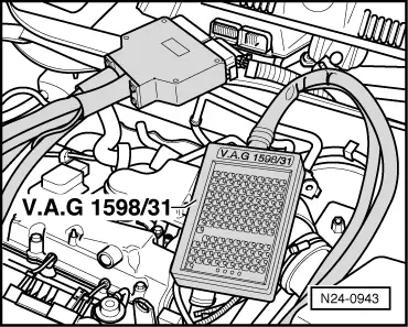
| Connect 121-pin adapter cable -V.A.G 1598/31- to engine control unit and reconnect 6-pin connector to exhaust gas recirculation valve -N18-. |
| –
| Connect fault reader -V.A.G 1551- or vehicle system tester -1552-. Then switch on ignition and select engine control unit with “Address word 01” → Rep. Gr.01. |
| –
| Initiate final control diagnosis and select exhaust gas recirculation valve -N18- → Rep. Gr.01. |
| –
| Connect voltage tester -V.A.G 1527B- to test box socket 108 and earth using auxiliary cables from auxiliary measuring set -V.A.G 1594A- or auxiliary measuring set -V.A.G 1594C-. The voltage tester -V.A.G 1527B- must flash. |
| –
| Proceed with final control diagnosis until completed. |
| –
| Press buttons 0 and 6 for function “End data transfer” and confirm entry with Q button. |
| –
| Renew following components, depending on prerequisite: |
| Voltage tester -V.A.G 1527B- flashes: |
| –
| Renew exhaust gas recirculation valve -N18- with exhaust gas recirculation potentiometer -G212-. |
| If no fault is detected in lines/wiring and the voltage tester -V.A.G 1527B- does not flash: |
|
|
|