volkswagen Workshop Repair Guides

Volkswagen Workshop Service and Repair Manuals

Checking secondary air pump motor V101 > < Removing and installing parts of secondary air system
Checking secondary air system
Special tools and workshop equipment required
t  Fault reader -V.A.G 1551- or vehicle system tester -V.A.G 1552- or vehicle diagnosis and service information system -VAS 5052-
t  Diagnostic cable -V.A.G 1551/3-
  Note
Vehicle system tester -V.A.G 1552- can be used instead of fault reader -V.A.G 1551-, however a print-out is not possible.
Test prerequisites
   
l  
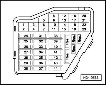
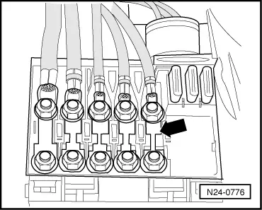
Fuse for secondary air pump relay -J299--arrow- in main fuse holder is OK.
l  The battery voltage must be at least 11.5 V.
l  All electrical consumers, e.g. lights and rear window heating, must be switched off.
l  Coolant temperature must be at least 80 °C, ⇒ display group 04, display zone 3.
l  Vacuum and pressure lines are not blocked, kinked and are not leaking.
l  Vehicle stationary.
l  Vehicles with automatic gearbox, selector lever must be in position “P” or “N”.
  N24-0776
l  All fuses must be OK.
Procedure
–  Connect fault reader -V.A.G 1551- or vehicle system tester -V.A.G 1552-. Start engine and run engine at idling speed. Select engine control unit with “Address word 01”. Connect fault reader and select engine control unit → Rep. Gr.01.
–  Read fault memory, if necessary, rectify fault and then clear fault memory → Rep. Gr.01.
Then:
t  Leave fault reader -V.A.G 1551- connected.
  N24-0588
Indicated on display:
–  Press buttons 0 and 4 for function “Initiate basic settings” and confirm entry with Q button.
 
Rapid data transfer                 HELP
Select function XX                    
Indicated on display:
–  Press buttons 0, 7 and 7 for “Display group number 77” and confirm entry with Q button.
 
Basic setting                        
Input display group number XXX       
Indicated on display: (1...4 = display zones)
–  Depress brake pedal and hold.
Vehicles 05.01 ►
–  Additionally depress accelerator pedal to full throttle position. Engine revolutions are raised by engine control unit to approx. 1400 rpm.
When diagnosis of engine control unit is initiated, display in display zone 4 jumps from “Test OFF” to “Test ON”.
–  Allow engine to continue to run at increased idling speed (brake pedal and if necessary accelerator pedal depressed) until the result of the functional test is displayed in display zone 4: Specification “Syst. OK”.
If the display does not indicate as described:
–  Take vehicle for a road test to free Lambda probe of any deposits, then repeat test.
–  Read fault memory → Rep. Gr.01.
If the display does again not indicate as described:
–  Check secondary air pump motor -V101- → Chapter.
If the display indicates as described:
–  Press the button.
–  Press buttons 0 and 6 for function “End output” and confirm entry with Q button.
 
System in basic setting 77            ->
        1       2       3       4       

Checking secondary air pump motor V101 > < Removing and installing parts of secondary air system