volkswagen Workshop Repair Guides

Volkswagen Workshop Service and Repair Manuals

Removing, installing and tensioning toothed belt > < Cylinder head
Removing and installing cylinder head
   
Removing and installing cylinder head
Special tools and workshop equipment required
t  Drip tray -V.A.G 1306- or drip tray for workshop hoist -VAS 6208-
t  Torque wrench -V.A.G 1332- (40...200 Nm)
t  Spring-type clip pliers -VAS 5024A-
t  Guide pins -3450/2A-
t  Removal tool -3450/3-
t  Polydrive key -3452- or special wrench, long-reach -T10070-

Prerequisites
l  The engine must be no more than warm to touch.
Procedure
  WARNING
When doing any repair work, especially in the engine compartment, pay attention to the following due to the cramped conditions:
t  
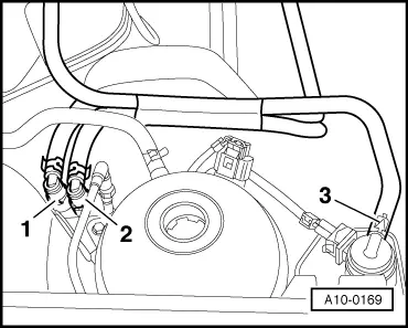
Route all the various lines (e.g. for fuel, hydraulics, activated charcoal filter system, coolant, refrigerant, brake fluid and vacuum) and electrical wiring in their original positions.
t  Ensure that there is sufficient clearance to all moving or hot components.
–  First check whether a coded radio is fitted. If so, obtain anti-theft coding.
–  With the ignition switched off, disconnect battery earth strap.
–  Remove engine cover.
–  Drain coolant → Chapter.
  WARNING
Fuel system is under pressure! Before opening the system place a cloth around the connection. Then release pressure by carefully loosening the connection.
   
–  Pull fuel supply line -1- and fuel return line -2- off connecting point.
–  Seal lines so that fuel system is not contaminated by dirt.
–  Pull hose off activated charcoal filter solenoid valve 1 -N80-.
–  Remove upper part of intake manifold.
–  Detach coolant, vacuum and intake hoses as necessary from upper part of intake manifold/cylinder head.
–  Pull off or disconnect all other electrical connections as necessary from cylinder head and lay to side.
  Note
Seal intake ports in lower part of intake manifold using a clean cloth.
–  Remove connection pipe for exhaust gas recirculation.
–  Unbolt coolant distributor housing.
–  Remove secondary air pump intake and pressure lines.
–  Unbolt secondary air pump motor -V101- and bracket and remove.
–  Unbolt front exhaust pipe with catalytic converter
–  Remove poly V-belt → Chapter.
–  Remove poly V-belt tensioning element.
–  Remove bracket on poly V-belt tensioning element.
–  Remove upper toothed belt guard.
  A10-0169
–  Set camshaft pulley to TDC No. 1 cylinder by turning crankshaft. Marking on camshaft pulley must align with arrow on toothed belt guard.
–  Release tensioning roller and remove toothed belt from camshaft toothed belt pulley.
–  Turn crankshaft back slightly.
  A13-0077
–  Remove camshaft sprocket. When loosening camshaft pulley bolt, hold with counterhold -3415-.
–  Remove Woodruff key from camshaft.
–  Remove rear toothed belt guard.
–  Loosen cylinder cover bolts from outside inwards.
–  Remove cylinder head cover.
  N15-0455
–  Loosen socket head bolts using special wrench, long reach -T10070- in sequence given and then remove completely.
–  Carefully remove cylinder head.
Installing
  Note
t  There must be no oil or coolant in the cylinder head bolt pockets in the cylinder head.
t  Do not remove new cylinder head gasket from its packing until immediately before installing.
t  Handle new gasket with extreme care. Damage will cause leakage.
–  Place clean cloths in cylinders so that no dirt or emery cloth particles can get in between cylinder wall and piston.
–  Also prevent dirt and emery cloth particles from getting into coolant.
–  Now carefully clean sealing surfaces of cylinder head and cylinder block. Ensure thereby that surfaces are not scored or scratched (if abrasive paper is used, grade must not be less than 100).
–  Carefully remove metal particles, emery residue and cloths.
–  If crankshaft is turned in the meantime, position piston of No. 1 cylinder at TDC and turn crankshaft back slightly.
  N15-0026
–  To centralise, screw guide pins -3450/2A- into front outer cylinder head bolt threaded holes.
–  Fit new cylinder head gasket. Inscription (Part No.) must be readable.
–  Fit cylinder head, screw in 8 remaining cylinder head bolts and tighten by hand.
–  Remove guide pins -3450/2A- through bolt holes using extractor -3450/3-. To do this, turn removal tool -3450/3- anti-clockwise until guide pins -3450/2A- are free.
–  Now insert last two cylinder head bolts and tighten them hand-tight also.
  N15-0208
–  Tighten cylinder head bolts in tightening sequence as follows:
–  Pre-tighten all bolts to 40 Nm.
–  Then tighten all bolts 1/4 turn (90°) further using a rigid wrench.
–  Then tighten all bolts again 1/4 turn (90°) further.
  Note
When camshaft is turned, crankshaft must not be at TDC. Danger of damage to valves and piston crowns.
Further assembly is basically the reverse of the dismantling sequence.
–  Install toothed belt and adjust valve timing → Chapter.
–  Install poly V-belt tensioning element. Specified torque: 25 Nm
–  Install poly V-belt → Chapter.
Filling with new coolant → Chapter.
  V15-0738

Removing, installing and tensioning toothed belt > < Cylinder head