volkswagen Workshop Repair Guides

Volkswagen Workshop Service and Repair Manuals

Checking fuel pressure regulator and holding pressure > < Checking components
Checking injectors for leaks and injection rate
   
Checking injectors for leaks and injection rate
Special tools and workshop equipment required
t  Remote control for V.A.G 1348 -V.A.G 1348/3A-
t  Adapter cable -V.A.G 1348/3-2-
t  Injection rate tester -V.A.G 1602-
t  Auxiliary measuring set -V.A.G 1594A- or auxiliary measuring set -V.A.G 1594C-
t  Adapter cable, 121-pin -V.A.G 1598/31-

Test prerequisite
l  The fuel pressure must be in order, checking → Chapter.
  WARNING
Fuel system is under pressure! Before opening the system, remove fuse 28 and place a cloth around the connection. Then release pressure by carefully loosening the connection.
Test procedure
   
–  Connect adapter cable, 121-pin -V.A.G 1598/31- to control unit wiring harness. The engine control unit remains disconnected.
–  Remove secondary air pump and bracket.
–  Remove lower part of intake manifold.
–  Pull connectors off injectors.
–  Pull off vacuum hose off fuel pressure regulator.
–  Remove fuel rail securing bolts.
  N24-0943
–  Pull fuel rail with injectors off intake manifold and lay on a clean cloth. Fuel lines remain connected.
–  Bridge test box sockets 1 and 80 using adapter cables cables from auxiliary measuring set -V.A.G 1594A- or auxiliary measuring set -V.A.G 1594C-.
  Note
This step serves only to have the fuel pump running when the engine is stopped.
–  Switch on ignition.
Checking for leaks
–  Check injectors for leaks (visual check). No more than 1 to 2 drops per minute must escape from each valve when fuel pump is running.
If the fuel loss is greater:
–  Switch off ignition and renew leaking injector.
  Note
t  If injectors are renewed, erase learnt values and adapt engine control unit again → Chapter.
t  Always renew seals.
Checking quantity injected
l  Adapter cable 121-pin -V.A.G 1598/31- still connected and the test box sockets 1 and 80 bridged with adapter cables from auxiliary measuring set -V.A.G 1594A- or auxiliary measuring set -V.A.G 1594C-.
l  Injectors installed in fuel rail and fuel lines connected.
–  Insert injector to be checked into measuring glass from injection rate tester -V.A.G 1602-.
  A24-0335
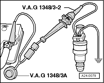
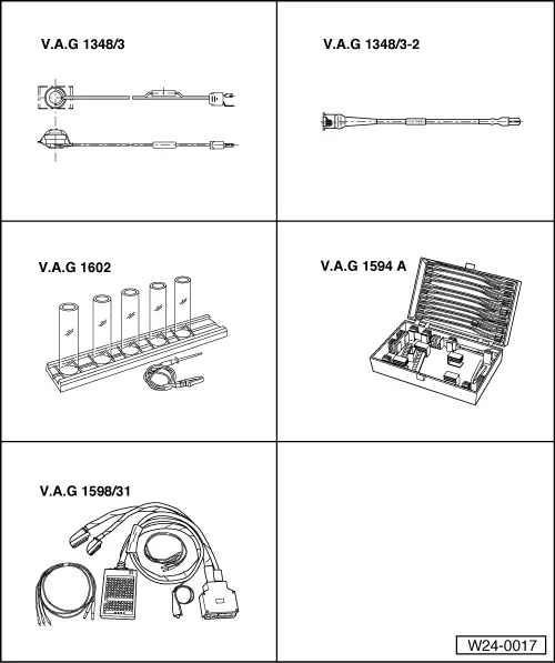
–  Connect a contact of injector to be tested to engine earth using adapter cable from auxiliary measuring set -V.A.G 1594A- or auxiliary measuring set -V.A.G 1594C-.
–  Connect second injector contact with auxiliary cable to remote control for V.A.G 1348 -V.A.G 1348/3A- using adapter cable -V.A.G 1348/3-2-.
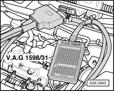
–  Connect crocodile clip to battery (+).
–  Switch on ignition; the fuel pump must run.
–  Operate remote control for V.A.G 1348 -V.A.G 1348/3A- for 30 seconds.
–  Repeat check on other injectors. Use new measuring beakers.
–  After all injectors have been activated, place measuring beakers on a level surface and compare the quantity injected. Specification: 85…105 ml per injector.
When checking the quantity injected, check the spray pattern as well. The spray patterns must be the same for all injectors.
If the measured values of one or more injectors are above or below the prescribed specifications:
–  Renew defective injector.
  Note
If injectors are renewed, erase learnt values and adapt engine control unit again → Chapter.
Install injectors in reverse order. When doing this, note the following:
t  Renew O-rings on all injectors and lightly moisten with clean engine oil.
t  
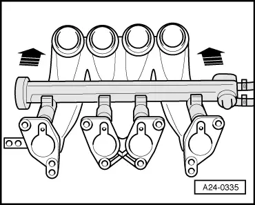
Insert injectors vertically and in the correct position into the fuel rail and secure with retaining clips.
t  Fit fuel rail with secured injectors onto intake manifold and press in evenly.
  A24-0079

Checking fuel pressure regulator and holding pressure > < Checking components