
Golf Mk4
| Removing and installing crankshaft |
 Note
Note| t | Before removing crankshaft, ensure that a suitable surface for storing crankshaft is prepared to ensure that sender wheel → Item is not damaged and is not touching any other item. |
| t | When working on engine, secure engine to repair stand -VW 313- using engine and gearbox support -VW 540- and engine and gearbox support supplement set -VW 540/1 B-. |

| 1 - | Oil pump. |
| q | Removing and installing → Chapter. |
| 2 - | 15 Nm |
| 3 - | Chain sprocket |
| q | For oil pump drive. |
| q | Check for wear. |
| 4 - | Bearing shells 1, 2, 4 and 5 |
| q | Approx. 05.00 ► classification for ordering spare parts → Fig.. |
| q | For bearing cap without oil groove. |
| q | For cylinder block with oil groove. |
| q | Do not interchange used bearing shells (mark). |
| 5 - | 65 Nm + 90 ° (1/4 turn) further |
| q | Renew. |
| q | Threaded along complete length. |
| q | Tighten crankshaft to 65 Nm when measuring radial clearance. |
| 6 - | Bearing cap |
| q | Bearing cap 1: Pulley end. |
| q | Bearing cap 3 with recesses for thrust washers. |
| q | Bearing shell retaining lugs in cylinder block and bearing caps must align. |
| 7 - | Bearing shell 3 |
| q | Approx. 05.00 ► classification for ordering spare parts → Fig.. |
| q | For bearing cap without oil groove. |
| q | For cylinder block with oil groove. |
| q | Do not interchange used bearing shells (mark). |
| 8 - | Sender wheel |
| q | Renew. |
| q | For engine speed sender -G28-. |
| q | Can only be installed in one position. Holes are offset. |
| 9 - | 10 Nm + 1/4 turn (90°) further |
| q | Renew. |
| 10 - | Thrust washer |
| q | For bearing cap, bearing 3. |
| q | Note fixing arrangement. |
| 11 - | Crankshaft |
| q | Axial clearance new: 0.07...0.23 mm, wear limit 0.30 mm. |
| q | Check radial clearance with Plastigage new: 0.01...0.04 mm, wear limit: 0.07 mm. |
| q | Do not rotate crankshaft when checking radial clearance. |
| q | Crankshaft dimensions → Chapter. |
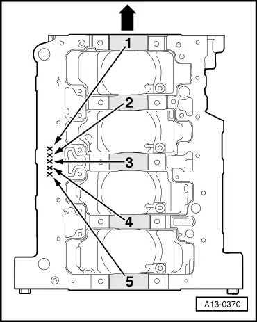
| Letter on cylinder block | Bearing colour | |
| S | = | Black. |
| R | = | Red |
| G | = | Yellow |
|