| –
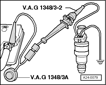
| Connect a contact of injector to be tested to engine earth using test lead from auxiliary measuring set -V.A.G 1594C-. |
| –
| Connect second injector contact with auxiliary cable to remote control for V.A.G 1348 -V.A.G 1348/3A- using adapter lead -V.A.G 1348/3-2-. |
| –
| Connect crocodile clip to battery (+). |
| Engine codes AGN, AGU, AQA, ARZ |
| –
| Initiate final control diagnosis with vehicle diagnosis, testing and information system -VAS 5051B-; fuel pump must run. |
| –
| Press key on display for “Vehicle self-diagnosis”. |
| –
| Press key “01 - Engine electronics” on display. |
| The control unit identification and coding are indicated on the display. |
| –
| Press key “03 - Final control diagnosis” on display. |

Note | t
| This step serves only to have the fuel pump running when the engine is not running. |
| t
| The final control diagnosis activates the injectors. The connector for the injectors must be disconnected before activating the final control diagnosis. |
| –
| Switch on ignition; the fuel pump must run. |
| Continuation for all engine codes |
| –
| Operate remote control for V.A.G 1348 -V.A.G 1348/3A- for 30 seconds. |
| –
| Repeat check on other injectors. Use new measuring beakers. |
| –
| After all injectors have been activated, place measuring beakers on a horizontal surface and compare the injection rate. |
| t
| AQA, ARZ, AUM, AUQ 133…157 ml for each injector |
| t
| AGN 85…105 ml for each injector |
| t
| AGU 110…130 ml for each injector |
| If the values measured for one or more injectors are above or below the specification: |
| –
| Renew defective injector. |
| Perform installation of injectors in reverse order. When doing this, note the following: |
| t
| Renew O-rings on all injectors and lightly moisten with clean engine oil. |
| t
| Insert injectors vertically and in the correct position into the fuel rail and secure with retaining clips. |
| t
| Fit fuel rail with secured injectors onto intake manifold and press in evenly. |
|
|
|
