
Golf Mk4
| Assembly overview |

| 1 - | Toothed belt guard upper part |
| 2 - | Main drive toothed belt |
| q | Check for wear. |
| q | Do not kink. |
| q | Removing, installing and tensioning → Chapter. |
| 3 - | Coupling drive toothed belt |
| q | Check for wear. |
| q | Do not kink. |
| q | Removing, installing and tensioning → Chapter. |
| 4 - | Inlet camshaft control valve 1 -N205- |
| 5 - | 10 Nm |
| 6 - | To intake hose |
| 7 - | Non-return valve |
| 8 - | Rubber grommet |
| 9 - | Cap |
| q | Renew seal if damaged. |
| 10 - | Seal |
| q | Renew if damaged. |
| 11 - | Oil filler neck |
| q | Renew. |
| 12 - | Cable guide |
| q | Bolt to camshaft housing with 10 Nm torque. |
| 13 - | Hall sender -G40- |
| 14 - | O-ring |
| q | Renew. |
| q | Lubricate before installing. |
| 15 - | High-pressure pump |
| q | For fuel supply. |
| q | Removing and installing → Chapter |
| 16 - | 10 Nm + 1/4 turn (90°) further |
| q | Renew. |
| q | Tighten from inside outwards. |
| 17 - | Camshaft housing |
| q | Removing and installing → Chapter |
| q | Remove sealant residue. |
| q | Coat with D 188 003 A1 before fitting. |
| q | When installing, fit vertically from above onto studs and dowel pins. |
| 18 - | Bracket |
| q | For wiring harness. |
| 19 - | Cylinder head bolt |
| q | Renew. |
| q | Sequence when loosening and tightening → Chapter. |
| 20 - | Connecting pipe |
| q | For exhaust gas recirculation. |
| 21 - | 20 Nm |
| 22 - | Gasket |
| q | Renew. |
| 23 - | Bracket |
| q | For coolant lines for engine oil cooler |
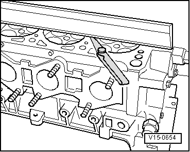
| 24 - | Cylinder head |
| q | Removing and installing → Chapter |
| q | Check for distortion → Fig.. |
| q | After renewing, renew entire coolant. |
| 25 - | Exhaust manifold |
| 26 - | Cylinder head gasket |
| q | Renew. |
| q | Metal gasket. |
| q | After renewing, renew entire coolant. |
| 27 - | Coupling drive tensioning roller |
| q | Check → Chapter. |
| q | Tensioning toothed belts → Chapter. |
| 28 - | Oil strainer |
| q | Clean strainer if soiled. |
| q | Note installation position. |
| 29 - | Rear toothed belt guard |
| 30 - | Lifting eye |
| 31 - | Gasket |
| q | Renew. |
| 32 - | Dowel pins |
| 33 - | Roller rocker finger |
| q | Check for ease of movement. |
| q | Check roller bearing for ease of movement. |
| q | Oil contact surfaces. |
| q | When installing, secure to supporting element using securing clip. |
| 34 - | Support element |
| q | Do not interchange. |
| q | With hydraulic valve clearance compensation. |
| q | Before installing, check camshaft axial clearance → Fig.. |
| q | Oil contact surfaces. |
|
|