
Golf Mk4
| Assembly overview |

| 1 - | Plug, 25 Nm |
| q | Renew. |
| 2 - | O-ring |
| q | Renew. |
| 3 - | 10 Nm |
| 4 - | Cover |
| 5 - | O-ring |
| q | Renew. |
| 6 - | Spring |
| 7 - | Central bolt for camshaft adjuster: 40 Nm + 1/4 turn (90°) further |
| q | Left-hand thread. |
| q | Removing and installing → Chapter. |
| q | Oil threads and bolt head contact surface before installing. |
| 8 - | Washer |
| q | Renew. |
| 9 - | Camshaft adjuster |
| q | Removing and installing → Chapter. |
| q | When renewing, also renew oil seal → Item. |
| 10 - | Inlet camshaft seal |
| q | Renew only with camshaft installed. |
| q | Lightly oil sealing lip of oil seal |
| q | Renewing → Chapter. |
| 11 - | Coupling drive toothed belt |
| q | Mark direction of rotation before removing. |
| q | Check for wear. |
| q | Do not kink. |
| q | Removing, installing and tensioning → Chapter. |
| 12 - | Exhaust camshaft |
| q | When installing note fixing arrangement. |
| q | Removing and installing → Chapter. |
| 13 - | Exhaust camshaft seal |
| q | Renew only with camshaft installed. |
| q | Lightly oil sealing lip of oil seal |
| q | Renewing → Chapter. |
| 14 - | Inlet camshaft control valve 1 -N205- |
| 15 - | 10 Nm |
| 16 - | 10 Nm + 1/4 turn (90°) further |
| q | Renew. |
| q | Tighten from inside outwards. |
| 17 - | Camshaft housing |
| q | Removing and installing → Chapter |
| q | Remove sealant residue. |
| q | Coat with D 188 003 A1 before fitting. |
| q | When installing, fit vertically from above onto studs and dowel pins. |
| 18 - | High-pressure pump |
| q | For fuel supply. |
| q | Removing and installing → Chapter |
| 19 - | Roller rocker finger |
| q | Check roller bearing. |
| q | Oil contact surface. |
| q | When installing, secure to supporting element using securing clip. |
| 20 - | Cotters |
| 21 - | Support element |
| q | Do not interchange. |
| q | With hydraulic valve clearance compensation. |
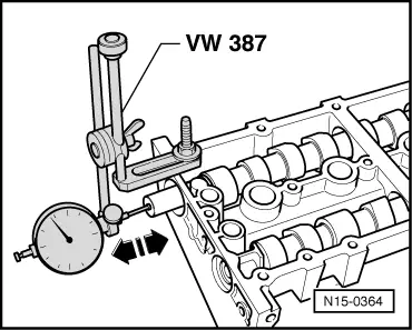
| q | Before installing, check camshaft axial clearance → Fig.. |
| q | Oil contact surface. |
| 22 - | Valve spring plate |
| 23 - | Valve spring |
| q | Removing and installing: |
| q | With cylinder head removed use valve spring compressor -3362- |
| q | With cylinder head installed → Chapter. |
| 24 - | Valve stem seal |
| q | Renewing → Chapter. |
| 25 - | Repair valve stem |
| q | With collar. |
| 26 - | Valve guide |
| q | Check → Chapter. |
| q | Renewing → Chapter. |
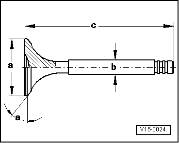
| 27 - | Valves |
| q | Do not rework, only lapping-in is permitted. |
| q | Valve dimensions → Fig.. |
| 28 - | Cylinder head |
| q | Reworking valve seat → Chapter. |
| q | Reworking sealing surface → Fig.. |
| 29 - | 20 Nm |
| 30 - | Coupling drive tensioning roller |
| q | Check → Chapter. |
| q | Tensioning toothed belts → Chapter. |
| 31 - | Oil strainer |
| q | Clean if soiled. |
| q | Note installation position. |
| 32 - | Retainer |
| q | For wiring harness. |
| 33 - | Cap |
| 34 - | Exhaust camshaft |
| q | Checking axial clearance → Fig.. |
| q | Coat with oil before inserting (also axial bearing shoulder). |
| q | After installing, renew oil seal. |
| q | Renewing seal → Chapter. |
| 35 - | Inlet camshaft |
| q | Checking axial clearance → Fig.. |
| q | Coat with oil before inserting (also axial bearing shoulder). |
| q | After installing, renew oil seal. |
| q | Renewing seal → Chapter. |
| 36 - | O-ring |
| q | Renew. |
| q | Moisten with oil before inserting. |
| 37 - | 20 Nm + 1/4 turn (90°) further |
| q | Renew. |
 Note
Note
|
|
Note
|
|
| Dimension | Inlet valve | Exhaust valve | |
| Ø a | mm | 29.5 | 26.0 |
| Ø b | mm | 5.973 | 5.953 |
| c | mm | 100.9 | 100.5 |
| α | ∠° | 45 | 45 |