volkswagen Workshop Repair Guides

Volkswagen Workshop Service and Repair Manuals

Fastening the engine to the assembly stand > < Removing and installing engine
4cyl. Injection Engine, (2.0 ltr. Engine) (Mexico)
Removing and installing engine
Notes on removing

Note:

During the further course of work the battery earth strap must be disconnected. Therefore please check first whether a coded radio is fitted. Obtain radio code first if necessary.

  • ‒ The engine is removed downwards together with the gearbox.
Warning:
When performing repair work, especially due to the confined conditions in the engine well, pay attention to the following:
  • ◆ Route all types of lines (e.g. for fuel, hydraulics, activated charcoal canister system, coolant, refrigerant, brake fluid and vacuum) as well as electrical wiring so that the original positions are restored.
  • ◆ Ensure sufficient clearance to all moving or hot components.
  • ‒ All cable ties which are opened or cut open when removing engine, must be replaced in the same position when installing the engine.
  • ‒ With the ignition switched off disconnect the battery earth strap.
  • ‒ Remove the engine cover.
  • ‒ Remove centre as well as the left and right-hand sound insulation:

=> General body repairs, exterior; Repair group 50; Noise insulation (petrol engine) - Assembly overview

  • ‒ Drain coolant .
  • ‒ Remove battery and battery retainer.

=> Electrical system; Repair group 27; Battery; Removing and installing battery

  • ‒ Observe rules for cleanliness .
Warning:
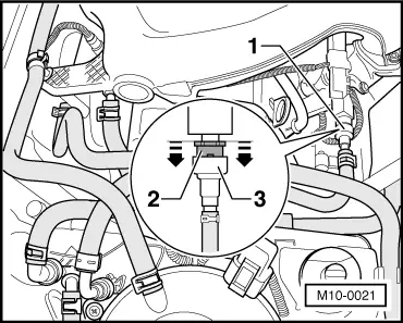
Fuel system is under pressure! Before opening the system place a cloth around the connection. Then release pressure by carefully loosening the connection.
 
M10-0021
  • ‒ → Pull fuel supply line -1- off union. To do this, press locking ring -2- into the union -3-.
  • ‒ Seal the pipes to avoid contamination of the fuel system.
  • ‒ Remove intake manifold upper part=> Page 24-24 .

Note:

Seal the intake ports in the intake manifold lower section with clean cloths.

  • ‒ In preparation for the further dismantling work disconnect the connectors from the following components:
    • Inlet camshaft timing adjustment valve (N205)
    • Ignition coils with final output stages (N70, N127, N291, N292)
    • Hall sender (G40)
    • Injectors (N30...N33), unclip cable guide
    • Coolant temperature sender (G62)
    • Engine speed sender (G28)
    • Knock sensor 1 (G61)
    • Knock sensor 2 (G66)
    • Secondary air pump motor (V101)
    • Oil pressure switch (F1)
    • Air mass meter (G70)
  • ‒ Remove air cleaner with air mass meter (G70), => page 24-17 .

Models with a manual gearbox

  • ‒ Disconnect shift mechanism from gearbox.

=> 5-speed manual gearbox 02J; Repair group 34; Servicing selector mechanism

  • ‒ Remove hydraulic clutch slave cylinder:

=> 5-speed manual gearbox 02J; Repair group 30; Servicing clutch control

Note:

The clutch pedal must not be operated.

Vehicles with automatic gearbox

  • ‒ Remove selector lever cable from gearbox:

=> Automatic gearbox 01M; Repair group 37; Servicing selector mechanism; Removing and installing cable

Continuation for all models

  • ‒ Remove poly V-belt => page 13-11 .
  • ‒ Remove securing clamps for power steering pressure pipe.
  • ‒ Remove power assisted steering vane pump with bracket and lay to side; hoses remain connected:

=> Running gear; Repair group 48; Assembly overview: Vane pump with hydraulic pipes

Vehicles with air conditioning

  • ‒ Remove air conditioner compressor.
  • ‒ Observe additional information and removal work => page 10-20 .

Continuation for all models

  • ‒ Disconnect hoses from engine.
  • ‒ Remove bracket for secondary air pump motor.
  • ‒ Disconnect all electric wires from gearbox, alternator and starter and move clear.
  • ‒ Pull off/disconnect all other electrical connections from engine and lay to one side as necessary.
 
A37-0200
  • ‒ → Unbolt pendulum support -arrows-.
  • ‒ Remove protective cover for right-hand inner constant velocity joint from engine.
  • ‒ Remove right-hand drive shaft and disconnect left-hand drive shaft at gearbox:

=> Running gear; Repair group 40; Removing and installing drive shafts

  • ‒ Remove front exhaust pipe => page 26-1 , Removing and installing parts of the exhaust system.
  • ‒ Pull connection for Lambda probe before catalytic converter off (=> Page 26-6 , Fig.1) and free wiring.
  • ‒ Remove oil sump protection , fig.2
 
N10-0056
  • ‒ Insert engine bracket T10012 in engine/gearbox jack V.A.G 1383 A.
  • ‒ → Secure engine bracket T10012 to front of cylinder block with securing bolt M10 x 25/ 8.8 to 40 Nm.
  • ‒ Tighten securing nut on exhaust side hand tight.
  • ‒ Lift engine and gearbox lightly using engine/gearbox jack V.A.G 1383 A.
 
A10-0125
  • ‒ → Unbolt engine side of assembly mounting from top of engine carrier -arrows-.

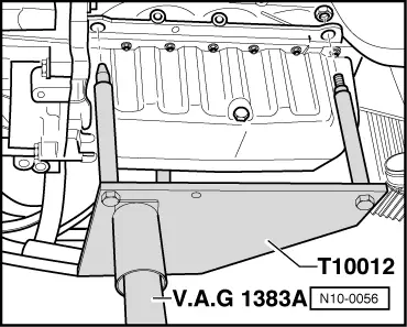
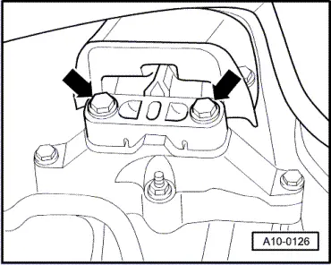
Note:

To remove securing bolts, use step ladder VAS 5085.

 
A10-0126
  • ‒ → Unbolt gearbox side of assembly mounting from top of gearbox carrier -arrows-.
  • ‒ Carefully lower engine with gearbox.

Note:

Engine and gearbox must be guided carefully when lowering to prevent damage to the bodywork, hoses and lines/wiring.

Fastening the engine to the assembly stand > < Removing and installing engine