volkswagen Workshop Repair Guides

Volkswagen Workshop Service and Repair Manuals

Checking fuel pressure regulator and holding pressure > < Checking components
4cyl. Injection Engine, (2.0 ltr. Engine) (Mexico)
Checking components
Checking injectors for leaks and quantity injected

Special tools, workshop equipment, testers, measuring instruments and auxiliary items required

  • ◆ V.A.G 1348/3 Remote control
  • ◆ V.A.G 1348/3-2 Adapter
  • ◆ V.A.G 1602 Calibration tester
  • ◆ V.A.G 1594 A Adapter set
  • ◆ V.A.G 1598/31 Test box

Test prerequisites

  • ● The fuel pressure must be in order, checking
    .
Warning:
Fuel system is under pressure! Before opening the system remove fuse 28 and place a cloth around the connection. Then release pressure by carefully loosening the connection.

Test sequence

  • ‒ Remove wiper arms and cowl panel:

=> Electrical system; Repair group 92; Windscreen wiper system; Removing and installing windscreen wiper system

 
N24-0943
  • ‒ → Connect test box V.A.G 1598/31 to control unit wiring harness. The engine control unit remains disconnected.
  • ‒ Remove intake manifold upper part .
  • ‒ Pull connector off all injectors.
  • ‒ Remove securing bolts on fuel rail.
  • ‒ Pull hose off air pipe for air shrouded injectors ( , item 5).
  • ‒ Lift fuel rail along with injectors off intake manifold and support.
  • ‒ Bridge test box sockets 1 and 65 using adapter cable from adapter set V.A.G 1594.

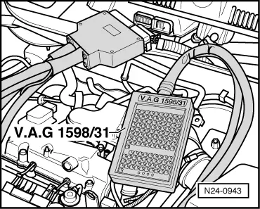
Note:

This work sequence allows the fuel pump to run when the engine is not running.
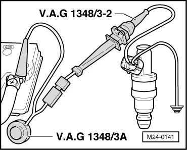
  • ‒ Switch on ignition.

Checking for leaks

  • ‒ Check injector for leaks (visual check). Only 1 to 2 drops per minute must emit from each injector when fuel pump is running.

If the fuel loss is greater:

  • ‒ Switch off ignition and renew leaky injector.
  • ‒ Erase the fault memory to return the learnt values to a neutral (default) position => page 24-46 , Interrogating and erasing fault memory

Note:

Always renew seals.

Checking quantity injected

Test prerequisites

  • ● Test box V.A.G 1598/31 still connected and test box sockets 1 and 65 are still bridged using adapter cables from adapter set V.A.G 1594.
  • ‒ Insert injector to be checked in a measuring glass of calibration tester V.A.G 1602.
 
M24-0141
  • ‒ → Connect one contact of the injector to be tested to engine earth using adapter cables from V.A.G 1594.
  • ‒ Using adapter cables connect the second injector contact to remote control V.A.G 1348/3 with adapter cable V.A.G 1348/3-2.
  • ‒ Connect crocodile clip to battery (+).
  • ‒ Switch on ignition, the fuel pump must run.
  • ‒ Operate remote control V.A.G 1348/3 for 30 seconds.
  • ‒ Repeat check on the other injectors. Use another (clean and dry) measuring beaker for this.
  • ‒ After all injectors have been activated, place the measuring glasses on a horizontal surface and compare the quantity injected.
         Specification: 85...105 ml per injector

If the measured values of one or more injectors are above or below the prescribed specifications:

  • ‒ Renew defective injector
  • ‒ Erase the fault memory to return the learnt values to a neutral (default) position => page 24-46 , Interrogating and erasing fault memory

Perform installation of injectors in reverse order. When doing this note the following:

  • ◆ Renew O-rings on all injectors and moisten then lightly with clean engine oil.
  • ◆ Insert injectors vertically and in the correct position into the fuel rail and secure with retaining clips.
  • ◆ Set fuel rail with secured injectors on intake manifold and press in evenly.

Checking fuel pressure regulator and holding pressure > < Checking components