
Golf Mk4
| Assembly overview - parts of cooling system, engine side |
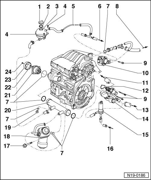
| 1 - | Cap |
| q | Check using cooling system tester -V.A.G 1274- and adapter for cooling system tester -V.A.G 1274/9-. |
| q | Test pressure: 1.4...1.6 bar. |
| 2 - | O-ring |
| q | Renew if damaged. |
| 3 - | Expansion tank |
| q | Carry out leakage test of cooling system using cooling system tester -V.A.G 1274- and adapter for cooling system tester -V.A.G 1274/8- |
| q | Test pressure: 1.4...1.6 bar. |
| 4 - | 10 Nm |
| 5 - | Upper coolant pipe |
| q | Clipped onto bulkhead |
| q | Coolant hose schematic diagram → Chapter |
| 6 - | To top of radiator |
| q | Coolant hose schematic diagram → Chapter |
| 7 - | O-ring |
| q | Renew |
| 8 - | To heat exchanger |
| q | Coolant hose schematic diagram → Chapter |
| 9 - | 10 Nm |
| 10 - | Throttle valve module -J338- |
| q | Heated by coolant. |
| 11 - | To top of radiator |
| q | Coolant hose schematic diagram → Chapter |
| 12 - | Gasket |
| q | Renew |
| 13 - | To bottom of radiator |
| q | Coolant hose schematic diagram → Chapter |
| 14 - | Thermostat housing |
| q | Dismantling and assembling → Chapter. |
| 15 - | Continued coolant circulation pump -V51- |
| q | Checking → Chapter. |
| 16 - | From heat exchanger |
| q | Coolant hose schematic diagram → Chapter |
| 17 - | 25 Nm |
| 18 - | Oil cooler |
| q | Removing and installing → Item. |
| 19 - | Sealing plug |
| 20 - | Coolant pipe |
| q | Coolant hose schematic diagram → Chapter |
| 21 - | Coolant pump |
| q | Note installation position. |
| q | Check for ease of movement. |
| q | If damaged or leaking, renew complete. |
| q | Removing and installing → Chapter. |
| 22 - | 8 Nm |
| 23 - | Pulley |
| q | For coolant pump. |
| 24 - | 20 Nm |