
Golf Mk4
 Note
Note
|

| 1 - | Gasket |
| q | Renew |
| 2 - | M8 - 25 Nm, M10 - 40 Nm |
| q | Renew |
| 3 - | Heat shield |
| 4 - | Bracket |
| 5 - | Lambda probe -G39-*, 50 Nm |
| q | Grease only the threads with “G 052 112 A3”; “G 052 112 A3” must not get into the slots on the probe body. |
| q | Remove and install with lambda probe open ring spanner set -3337-. |
| q | Checking lambda control: → Motronic injection and ignition system (5-cyl. engine); Rep. Gr.24 |
| 6 - | 10 Nm |
| 7 - | Clip |
| 8 - | Catalytic converter |
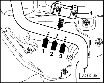
| 9 - | Double clamp |
| q | Note installation position → Fig.. |
| 10 - | 40 Nm |
| 11 - | Mounting |
| 12 - | Centre and rear silencer |
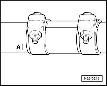
| q | Middle and rear silencers are installed as a single component during production. In cases of repair, the centre and rear silencer are supplied separately, with a double clamp for connecting. |
| q | Separating point: → Fig. |
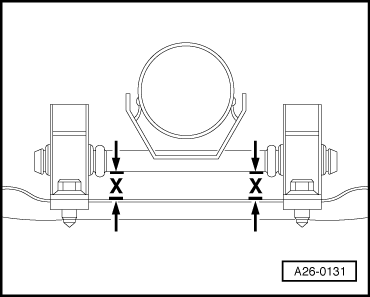
| q | Aligning rear silencer free of stress → Fig. |
| 13 - | Mounting |
| q | With support ring. |
| 14 - | Tunnel bridge |
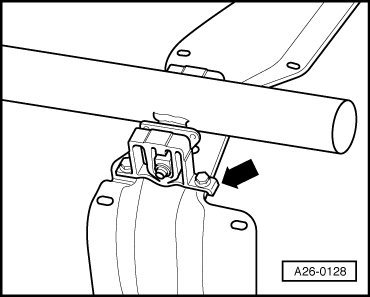
| 15 - | Mounting |
| q | Note installation position → Fig.. |
| 16 - | Heat shield |
| q | For catalytic converter |
| 17 - | Front exhaust pipe with catalytic converter |
| 18 - | Gasket |
| q | Renew |
| 19 - | Exhaust manifold |
| q | Tighten securing nuts on flange to exhaust pipe in diagonal sequence |
|
|
Note
|
|
|
|