Golf Mk4
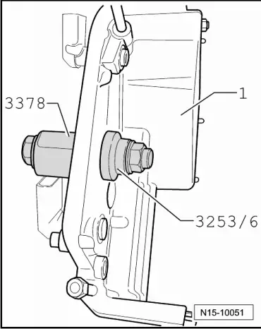
| Assembly overview - cover |

| 1 - | Cable guide |
| q | For coolant hoses and wiring harness |
| q | Coolant hose schematic diagram → Chapter. |
| 2 - | 8 Nm |
| 3 - | Hall sender 2 -G163- |
| q | For exhaust camshaft. |
| q | Before removing, mark connector belonging to component. |
| 4 - | Chain tensioner, 40 Nm |
| q | For camshaft timing chain → Item |
| q | Only rotate engine when chain tensioner is installed. |
| 5 - | Seal |
| q | Renew if damaged or leaking. |
| 6 - | Bracket |
| q | For wiring harness and earth connection |
| 7 - | Bracket |
| q | For continued coolant circulation pump -V51- |
| 8 - | Continued coolant circulation pump -V51- |
| q | Coolant hose schematic diagram → Chapter. |
| q | Checking → Chapter |
| 9 - | Seal |
| q | For camshaft adjuster valve 1 -N205- → Item and exhaust camshaft adjuster valve 1 -N318- → Item |
| q | Renew if damaged or leaking. |
| q | Installing → Fig.. |
| 10 - | 23 Nm |
| 11 - | Bracket |
| q | For wiring harness. |
| 12 - | Thermostat housing |
| q | Removing and installing → Chapter |
| q | Assembly overview → Chapter. |
| q | Coolant hose schematic diagram → Chapter. |
| 13 - | Seal |
| q | Renew. |
| 14 - | Cover |
| q | Coat sealing surfaces with sealant „D 176 501“. |
| q | Preparing cylinder head gasket for assembly → Fig.. |
| 15 - | Hall sender -G40- |
| q | For inlet camshaft. |
| q | Before removing, mark connector belonging to component. |
| 16 - | O-ring |
| q | For sealing oil channel. |
| q | Renew. |
| q | Lubricate before installing. |