
Golf Mk4
| Assembly overview - cylinder head |
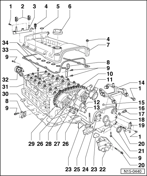
| 1 - | 10 Nm |
| 2 - | Bracket |
| q | For fuel lines |
| 3 - | Retaining frame |
| 4 - | 10 Nm |
| q | With spacer sleeve and seal. |
| q | Renew seal if damaged. |
| 5 - | O-ring |
| q | Renew if damaged. |
| q | Lubricate before installing. |
| q | For ignition coil with output stage. |
| 6 - | Cap |
| q | Renew seal if damaged. |
| 7 - | Cylinder head cover |
| q | Removing and installing → Chapter |
| q | Renew if damaged. |
| 8 - | Lifting eye |
| 9 - | 23 Nm |
| 10 - | Camshaft timing chain |
| q | Before removing, mark direction of rotation (installation position) → Fig.. |
| q | Renew. → Chapter. |
| 11 - | Combination valve |
| q | Removing and installing → Chapter |
| q | Checking → Chapter |
| 12 - | Inlet camshaft adjuster valve 1 -N205- |
| q | For inlet camshaft. |
| q | Before removing, mark connector belonging to component. |
| 13 - | Exhaust camshaft adjuster valve 1 -N318- |
| q | For exhaust camshaft. |
| q | Before removing, mark connector belonging to component. |
| 14 - | Bracket |
| q | For wiring harness. |
| 15 - | O-ring |
| q | For sealing oil channel. |
| q | Renew. |
| q | Lubricate before installing. |
| 16 - | Hall sender 2 -G163- |
| q | For exhaust camshaft. |
| q | Before removing, mark connector belonging to component. |
| 17 - | Chain tensioner, 40 Nm |
| q | For camshaft timing chain → Item |
| q | Only rotate engine when chain tensioner is installed. |
| 18 - | Seal |
| q | Renew if damaged or leaking. |
| 19 - | Bracket |
| q | For wiring harness and earth connection |
| 20 - | 8 Nm |
| 21 - | Seal |
| q | For inlet camshaft adjuster valve 1 -N205- → Item and exhaust camshaft adjuster valve 1 -N318- → Item |
| q | Renew if damaged or leaking. |
| q | Installing → Fig.. |
| 22 - | Thermostat housing |
| q | Removing and installing → Chapter |
| q | Assembly overview → Chapter. |
| q | Coolant hose schematic diagram → Chapter. |
| 23 - | Seal |
| q | Renew. |
| 24 - | Hall sender -G40- |
| q | For inlet camshaft. |
| q | Before removing, mark connector belonging to component. |
| 25 - | Cover |
| q | Can be removed and installed with engine installed. |
| q | Removing and installing → Chapter |
| q | If only cover has been removed, prepare cylinder head gasket for assembly → Fig.. |
| q | With O-ring for sealing oil channel → Item |
| 26 - | 60 Nm + 1/4 turn (90°) further |
| q | Renew. |
| q | Contact surface of sender wheel must be dry around bolt head when assembled. |
| q | To remove and install counterhold with 32 mm open-end spanner on camshaft → Chapter |
| 27 - | Exhaust camshaft adjuster |
| q | Identification: 32A. |
| q | Rotate engine only with camshaft adjuster installed. |
| q | Removing and installing → Chapter |
| 28 - | Guide rail |
| q | For camshaft timing chain → Item |
| q | Clipped into valve timing housing. |
| 29 - | Inlet camshaft adjuster |
| q | Identification: 24E |
| q | Rotate engine only with camshaft adjuster installed. |
| q | Removing and installing → Chapter |
| 30 - | Cylinder head gasket |
| q | Metal gasket. |
| q | Renew. |
| q | After renewing, renew entire coolant. |
| 31 - | Cylinder head |
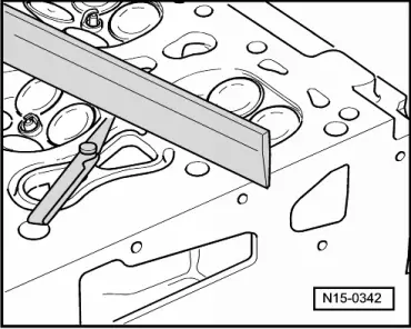
| q | Check for distortion → Fig.. |
| q | Removing and installing → Chapter |
| q | After renewing, renew entire coolant. |
| 32 - | Tensioning element |
| q | For poly V-belt. |
| q | Removing and installing poly V-belt → Chapter. |
| 33 - | Cylinder head bolt |
| q | Renew. |
| q | Follow installation instructions and sequence when loosening and tightening → Chapter. |
| 34 - | Gasket for cylinder head cover |
| q | Renew if damaged or leaking. |
| q | Note installation position. |
|
|