volkswagen Workshop Repair Guides

Volkswagen Workshop Service and Repair Manuals

Installing > < Removing and installing intake manifold
Removing
Removing
  Note
Before carrying out further work, disconnect battery earth strap. First check whether a coded radio is fitted. Obtain anti-theft coding first if necessary.
–  With the ignition switched off, disconnect battery earth strap.
–  All cable ties which are opened or cut open when engine is removed must be replaced in the same position when engine is installed.
–  Remove engine cover.
–  For engine codes AQP and AUE remove spark plug connectors and unclip ignition cables.
   
–  For engine codes BDE, BFH, BJS and BML remove ignition coils with output stages for cylinders 1-6 using puller -T10095 A- → Chapter.
–  Remove intake hose between air mass meter -G70- and throttle valve module -J338-: → Chapter
  N28-0256
–  Detach 6-pin connector from throttle valve module -J338--arrow-.
–  Detach earth connection on throttle valve control module -J338-.
  WARNING
Steam may escape when expansion tank is opened. Wear eye protection and protective clothing to avoid eye injuries and scalding. Cover cap with cloth and open carefully.
–  Open and close expansion tank cap to release pressure in cooling system.
–  Detach coolant hoses from throttle valve control unit -J338- and seal hose ends.
–  Unscrew coolant and connecting hoses → Item and → Item, vacuum connection → Item and → Item behind intake manifold.
  N15-0477
–  Now pull vacuum lines -arrows- off intake manifold.
–  Unbolt intake manifold supports on left and right of intake manifold.
–  Unscrew bolt -1- for rear intake manifold support.
  WARNING
Fuel system is under pressure! Wear eye protection and protective clothing to avoid possible injury and skin contact. Before loosening hose connections, wrap a cloth around the connection. Then release pressure by carefully pulling hose off connection.
  N15-0313
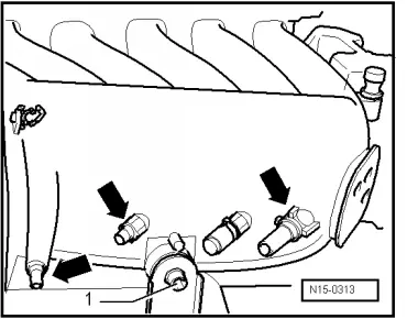
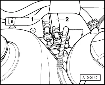
–  Detach supply line -1- (white marking) and return line -2- (blue marking) and collect any escaping fuel with cloth.
  Note
Press buttons on hose couplings to do this.
–  Seal lines so that fuel system is not contaminated by dirt.
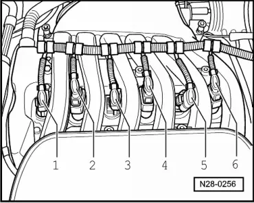
–  Unclip fuel and vacuum lines from cylinder head cover.
–  Remove the two bolts on the side for the intake manifold support.
–  Remove centre, left and right insulation trays: → General body repairs, exterior; Rep. gr.50
–  Remove front bumper cover → General body repairs, exterior; Rep. gr.63.
–  Remove retaining clamp(s) for refrigerant lines.
  WARNING
The air conditioner refrigerant circuit must not be opened.
–  Bring lock carrier into service position → General body repairs, exterior; Rep. gr.50.
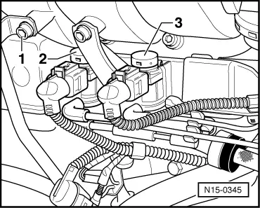
–  Detach connecting hose from cylinder head cover.
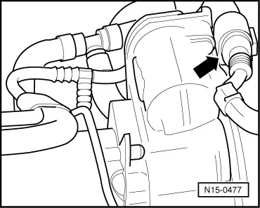
–  Detach vacuum hose from combination valve.
–  Unclip pressure hose and all other lines from brackets on intake manifold and cylinder head cover.
  A10-0140
–  Unscrew dipstick guide tube from intake manifold -1-.
–  Unclip secondary air inlet valve -2- and valve for intake manifold changeover -3- from vacuum reservoir.
  Note
The connectors for the valves can remain connected.
–  Detach vacuum hose from intake manifold change-over vacuum actuator.
–  Remove intake manifold securing bolts → Item from cylinder head.
–  Remove intake manifold and place it on a suitable surface so that the vacuum unit will not be damaged.
  Note
Seal intake ports in intake manifold and in cylinder head with a clean cloth.
  N15-0345

Installing > < Removing and installing intake manifold